


Communication Manager Maintenance-Object Repair Procedures
2332 Maintenance Procedures for Avaya Communication Manager 3.0, Media Gateways and Servers
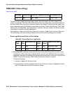
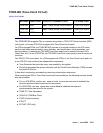
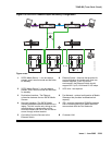
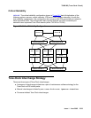
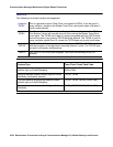
Figure 141: High-Reliability Configuration
Systems with the High Reliability Option (duplicated SPE, simplex PNC) have one Tone-Clock
circuit pack in each Port Network control carrier, A and B. One Tone-Clock circuit pack will be
actively generating system clock signals for Port Network components, while the other will be in
standby mode, ready to take over in the event of a Tone-Clock interchange. Similarly, one
Tone-Clock circuit pack will be actively providing system tones for the Port Network, while the
other will be in standby mode. Normally, the same Tone-Clock circuit pack will be active for both
tones and clock signals, but these responsibilities may be divided if neither circuit pack is able
to perform both functions. The status port-network command indicates which Tone-Clock
circuit pack is actively performing each function.
For systems using the TN2182 Tone-Clock-Detector circuit pack, tone generation and clock
generation behaves the same as other clock boards with one being active and one being
standby. But the tone detector ports (ETR-PTs) of the TN2182 are always considered available
and in-service regardless of the active/standby state of the tones or clock for a specific circuit
pack.
EPN Tone-Clock circuit pack configuration is the same as for the Standard Reliability Option.
Each EPN Tone-Clock circuit pack will be active for both tones and clock signals for its port
network.
EI
PN 3
Server A Server B
IPSI IPSI
EI
PN 2
IPSI IPSI
EI
PN 1
Control Network A Control Network B
Bearer Network
T/C