


Communication Manager Maintenance-Object Repair Procedures
1180 Maintenance Procedures for Avaya Communication Manager 3.0, Media Gateways and Servers
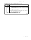
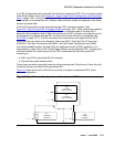
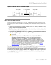
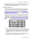
Figure 64: Center Stage Switch Configuration with Duplicated PNC
In a duplicated center stage switch configuration, two EIs are needed in each PN. One resides
in the PNC’s A side and one in the B side. Note that a PNC designation (A or B) does not
directly designate the carrier where an EI resides. The active PNC’s EI is the one acting as the
PN’s Archangel (TDM bus master). This EI’s amber LED should be blinking at a rate of
2 seconds on and 200 ms off. Whereas, the amber LED on standby PNC’s EI should be off.
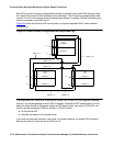
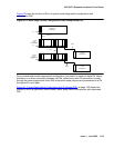
A PN (and thus, the EIs contained within it) can be remoted via a DS1 Converter complex. This
requires that a fiber link (providing connectivity to the remoted PN) be administered with an
associated DS1 Converter complex. This complex consists of two TN574 DS1 Converter
(DS1C-BD) circuit packs connected by from 1 to 4 DS1 facilities. Figure 65: Fiber Link with
DS1 Converter Complex on page 1181 shows where the DS1 converter complex fits into an
EI-to-SNI or EI-to-EI fiber link. For more information, see DS1C-BD
on page 1077.
FIBER
FIBER
A-PNC
FIBER
FIBER FIBER
21
21
10
1 1
1 2 10
13
13 1 2 10 12
N N
N
N N N
N
I I I I I
I
I
I
I I
C C
C C
CARRIER D
SN #1
SN #1
CAB 1
CAB 1
CARRIER D
Slot #
Slot #
EPN EPN
CAB 2
CAB 2
CARRIER B
CARRIER B
CARRIER A CARRIER A
CAB 3
CAB 3
Slot #
Slot #
SN #2
SN #2
CAB 2
CAB 2
CARRIER E
CARRIER E
E
E
E
E
E
E
I
I I
I I
I
S S S S S S S
S S
S
S S S
S
N N N N N N N
1
2
2
2 10
13
13 2 1
20
20
B-PNC
METALLIC
METALLIC
CABLE
CABLE
FIBER