


DS1C-BD
Issue 1 June 2005 1099
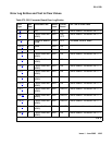
q. Error Type 769, Aux Data 7: A minor on-board hardware failure exists on the processor/
control hardware on the DS1 converter circuit pack. Replace the DS1 converter circuit pack.
r. Error Type 1281: For TN574 DS1 converter boards, this error indicates that the facility
masks or the clock reference masks do not match between the two DS1 converter circuit
packs in the DS1 converter complex.
For TN1654 DS1 converter boards, this error indicates that the facility masks do not match
between the two DS1 converter circuit packs in the DS1 converter complex.
Alarm should clear in 15 minutes.
1. If the problem persists, reset both DS1 converter circuit packs in the DS1 converter
complex via reset board.
2. If the problem persists, replace this DS1 converter circuit pack.
3. If the problem persists, replace the DS1 converter circuit pack at the other end of the DS1
converter complex.
s. Error Type 1537: The two TN574 DS1 converter circuit packs in the DS1 converter
complex do not have the same firmware vintage. The TN574 DS1 converter with the older
vintage should be replaced. This error does not apply to TN1654 boards.
t. Error Type 1793: Fiber Loss of Frame Alignment (LFA) alarm occurred at the other end of
the DS1 converter complex. The DS1 converter circuit pack at the other end of the DS1
converter complex cannot frame up on the signal coming into the circuit pack from the fiber.
(The neighbor DS1 converter circuit pack detected the LFA and relayed this information to
this DS1 converter circuit pack via the DS1 control channel.) The amber LED will flicker at a
5-Hz rate (on for 0.1 second, off for 0.1 second).
1. Execute list fiber-link to determine the Fiber Endpoint that is connected to the
DS1 converter circuit pack. Enter display errors and follow the associated repair
procedures for any EXP-INTF, and SNI-BD errors for the Fiber Endpoints. Enter
display errors and follow the associated repair procedures for any FIBER-LK errors
for this fiber link.
2. If the problem still persists, check for excessive slips and synchronization problems.
Enter display errors and follow the associated repair procedures for any SYNC,
TDM-CLK, and SNC-BD errors.
3. If the problem still persists, run the Far-End DS1 converter Circuit Pack Loopback test
(#788) on this DS1 converter circuit pack via test board location long. This test
indicates if the neighbor DS1 converter circuit pack hardware is functioning. If the test
fails, replace the DS1 converter circuit pack at the other end of the DS1 converter
complex.
4. If the problem still persists, run the Far-End Fiber Optic Terminator (lightwave
transceiver) Loopback test (#789) on this DS1 converter circuit pack via test board
location long. If this test fails, replace the lightwave transceiver that is connected to
the neighbor DS1 converter circuit pack at the other end of the DS1 converter complex. If
the neighbor board is connected to the Fiber Endpoint via metallic cable, this test aborts.