


Communication Manager Maintenance-Object Repair Procedures
2130 Maintenance Procedures for Avaya Communication Manager 3.0, Media Gateways and Servers
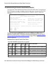
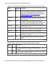
Stratum-3 Clock LED Strategy
Note:
Note: When looking in the Stratum-3 cabinet, “A” card is on the left and “B” card is on
the right.
Note:
Note: The normal LED scheme is not followed for this device. Green LEDs do not
indicate maintenance activity. There are no yellow LEDs, and there are more
than three LEDs per circuit pack.
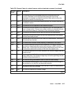
Note:
Note: Removal of a card in the Stratum-3 clock may cause alarm(s) to be resolved and
the query test to pass. However, the removed cards should still be replaced to
restore the Stratum-3 clock to full service.
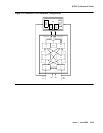
The Stratum-3 clock has the following components:
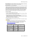
● 2 Clock Input cards (CI)
Provides the logic to select the better DS1 reference or Clock Input card. The red FAIL LED
on this card indicates a failure with the card or the DS1 reference connected to it.
● 2 Stratum-3 Cards (ST3)
Provides 24-hour holdover. The red FAIL LED on this card indicates a failure with the card.
Replace the card.
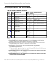
● 2 Timing Output Cards (TOC)
Provides cable length compensation, multiple output ports, selection of the ST3, and CI
outputs. This type of card has two red failure LEDs: one indicates a failure of the card; the
other indicates a failure in one or more output ports. In either case, replace the card.
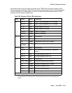
● 1 PBX (Private Branch Exchange) Alarm Interface (PAI)
Filters power supplied to the clock, provides fuse protection, and provides alarm indications
based on inputs supplied by other cards. The six LEDs on this card provide indications for
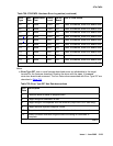
the six alarm or status conditions as follows:
- Loss of DS1 reference A
- Loss of DS1 reference B
- Loss of one clock unit
- Loss of both clock units
- Loss of one power supply
- Loss of both power supplies