


ETR-PT (Enhanced Tone Receiver Port)
Issue 1 June 2005 1167
ETR-PT (Enhanced Tone Receiver Port)
S8700 | 8710 / S8500
Note:
Note: Replacing the Tone-Clock circuit pack requires a special procedure which is
described in TONE-BD (Tone-Clock Circuit)
on page 2327. That section also
describes the LED display for this board.
The ETR-PT MO is supported by TN2182, TN2312AP and TN2312BP circuit packs.
TN2312AP IPSI Circuit Pack’s Tone-Clock
For a PN with a TN2312 IPSI, the TONE-BD MO is a module located on the IPSI circuit pack. It
provides tone generation, tone detection, call classification, and clock generation and
synchronization. The TN2312 replaces the TN2182B Tone-Clock board and is inserted into
each PN’s Tone-Clock slot. For a non IPSI PN, the TN2182B Tone-Clock circuit packs provide
the previous functions.
The TN2312 IPSI circuit pack (for PNs equipped with IPSIs) or the Tone-Clock circuit packs (for
non IPSI PNs) both house two independent components:
● Tone Generator that provides every tone needed by the system
● Clock that generates clocks for both the system’s Time Division Multiplex (TDM) bus and
the LAN bus. It also aids in monitoring and selecting internal synchronization references.
When resolving errors/alarms on an IPSI or Tone-Clock circuit pack, the following sections
should also be consulted:
● For a non IPSI PN, use set tone-clock UC to establish the tone and synchronization
resources for the system.
● For an IPSI PN, use set ipserver-interface UC to establish the tone and
synchronization resources for the system.
● TONE-PT (Tone Generator)
● TDM-CLK (TDM Bus Clock)
● SYNC (Synchronization)
● TONE-BD
● PKT-INT (IPSI only)
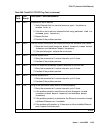
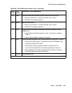
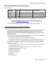
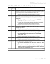
MO Name in
Alarm Log
Alarm
Level
Initial SAT Command to Run Full Name of MO
ETR-PT MAJ test port location sh Enhanced Tone Receiver Port
ETR-PT MIN test port location sh Enhanced Tone Receiver Port
ETR-PT WRN test port location sh Enhanced Tone Receiver Port