


Communication Manager Maintenance-Object Repair Procedures
2168 Maintenance Procedures for Avaya Communication Manager 3.0, Media Gateways and Servers
4. Enter test tone-clock location long to test the active Tone-Clock circuit pack in
the master port network.
Check the Error Log for TDM-CLK errors, and verify that TDM Bus Clock Circuit Status
Inquiry test (#148), passes.
If Test #148 fails with Error Code 2–32, see TDM-CLK (TDM Bus Clock)
on page 2252 to
resolve the problem. If not, continue with the following.
5. Use disable synchronization-switch and enable
synchronization-switch. When these two commands are used together, they
change the system synchronization reference to the primary DS1 Interface circuit pack.
6. Check the Error Log and use status synchronization to verify that the primary DS1
Interface circuit pack is still the system synchronization reference.
If the primary DS1 Interface circuit pack is not the system synchronization reference, and
the master port network does not have duplicate Tone-Clock circuit packs, escalate the
problem.
Otherwise, continue with the following.
7. For duplicated Tone-Clock circuit packs in the master port network:
Enter set tone-clock location to interchange Tone-Clocks in the master port
network, and repeat the disable/enable commands described in the previous step.
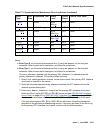
c. This error indicates that Synchronization Maintenance was disabled using disable
synchronization-switch. Use enable synchronization-switch to enable
Synchronization Maintenance reference switching and to resolve this alarm.
d. This error indicates a problem with the secondary DS1 reference. It is cleared when the
secondary reference is restored. Refer to note (b
) to resolve this error substituting
secondary for primary in the preceding resolution steps.
e. This error indicates that the Tone-Clock circuit pack is providing the timing source for the
system. The primary and secondary (if administered) are not providing a valid timing signal.
Investigate errors 1 and 257 to resolve this error.
f.
S8700 MC: This error indicates that the external Stratum-3 clock failed to provide the
system’s timing reference. Refer to Stratum-3 clock’s Maintenance document to resolve the
defective synchronization reference.
g. This error indicates excessive switching of system synchronization references has
occurred. When this error occurs, synchronization is disabled and the Tone-Clock circuit
pack (in the master port network) becomes the synchronization reference for the system.
Execute the following steps to resolve this error:
1. Check for timing loops, and resolve any loops that exist.