


DS1C-BD
Issue 1 June 2005 1081
To administer a standard-, duplex-, or high-reliability system (no PNC duplication):
1. Administer carriers via add/change cabinet.
2. Administer circuit packs via change circuit-pack.
3. Administer connectivity and the facility options of the DS1 converter complex via add/
change fiber-link.
To administer a critical-reliability system (PNC duplication):
1. Enable PNC duplication feature using the change system-parameter
customer-option.
2. Administer carriers via add/change cabinet.
3. Administer circuit packs via change circuit-pack.
4. Administer connectivity and the DS1 facility options of each DS1 converter complex via
add/change fiber-link.
5. Turn on PNC duplication via change system-parameter duplication.
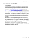
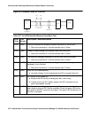
TN1654 Board Configuration Switch Settings
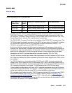
The TN1654 DS1 converter circuit pack is field configurable for T1 or E1 operation so that a
single board serves worldwide application. All four DS1 facilities are configured to either T1 or
E1 as a group via an option switch located on the component side of the circuit pack. If T1
operation is selected, four additional switches are used to select the framing mode for each
facility. Each facility can be set to either D4 or ESF framing. If E1 operation is selected, the
same four switches are used to select the E1 facility line termination impedance. The E1 line
termination impedance for each facility can be set to either 120Ω
for twisted-pair or 75Ω for
coaxial wiring.
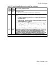
T1 or E1 operation must also be administered for the TN1654 DS1 converter board on the
fiber-link screen via the Bit Rate field. An error will be logged and an alarm will be raised if
there is a T1/E1 inconsistency between the administered bit rate and the board option switch
setting.
The T1 facility framing mode and the E1 facility line termination impedance are defined by the
option switch settings only. Administration of these values is not allowed. The fiber-link screen
will display the selected option switch settings for each facility.
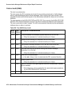
DS1 Converter LEDs
The TN574 board has seven LEDs on its faceplate. The TN1654 board has eleven LEDs on its
faceplate. The top three system standard LEDs are used to provide an indication of the state of
the DS1 converter board. These LEDs are under firmware control until the board has
established a link to the media server via the EI or SNI. Once the link is established, software
controls the three LEDs. If the link breaks, the LEDs are again under firmware control.