


Communication Manager Maintenance-Object Repair Procedures
1082 Maintenance Procedures for Avaya Communication Manager 3.0, Media Gateways and Servers
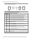
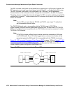
The red and green LEDs have the traditional use where red means an alarm condition and
green indicates that maintenance testing is in progress. The red and green LED is also turned
on during circuit pack initialization by firmware. When the control link to the circuit pack is lost,
firmware controls the red LED to indicate an alarm condition.
The amber LED under firmware control is used to indicate the state of the:
● Physical fiber interface
● Fiber channel (link to EI or SNI)
● DS1 control channel (link to opposite DS1 converter board)
● Server communications link
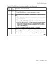
in the following manner and descending order of priority. (The amber LED stays lit longer as the
DS1 converter complex approaches full operation.)
1. If the fiber is out of frame or is in a loss-of-signal condition, the amber LED will flicker at a
5-Hz rate (on for 0.1 second, off for 0.1 second).
2. If the fiber channel is down (DS1 Converter circuit pack/fiber endpoint communications), the
amber LED will flash at a 1-Hz rate (on for ½ second, off for ½ second).
3. If the DS1 control channel is down between the two DS1 converters in the DS1 converter
complex, the amber LED will pulse at a 1/2-Hz rate (on for 1 second, off for 1 second).
4. If the media server communications link is down, the amber LED will wink off every 2
seconds for 200 msec (2 seconds on, 0.2 second off).
5. If all is well with the Fiber Interface and every communications channel, the amber LED will
remain on continuously in a standard-, duplex-, or high-reliability system. In a
critical-reliability system (duplicated PNC):
- An active DS1 converter circuit pack’s amber LED remains on continuously.
- A standby DS1 converter circuit pack’s amber LED remains off.
The LED will then be under software control.
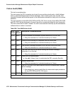
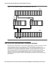
The bottom four green LEDs on the TN574 DS1 converter board are under hardware control.
The four green LEDs indicate, for each DS1 converter facility, whether a receive signal is
present for the DS1 facility.
The next four LEDs on the TN1654 DS1 converter board are labeled STATUS LEDs and are for
future use. These LEDs will not be lit.
The bottom four LEDs on the TN1654 board are labeled SPAN LEDs. These LEDs are under
firmware control. If the facility is not administered, then the LED is not lit. The LED is lit amber if
the facility is running alarm free. If the facility is detecting either a red alarm (loss-of-signal or
loss-of-frame), a yellow alarm (remote frame alarm) or a blue alarm (AIS signal) then the LED is
lit red. The SPAN SELECT Switch on the TN1654 faceplate is for future use. Pushing the switch
will have no affect on the board.