


ATM-TRK (Circuit Emulation Service Circuit Pack)
Issue 1 June 2005 625
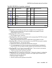
22 High-level Path
Alarm
Indication
Signal:
HP_AIS
The payload is invalid.
1. Make sure the ATM switch port (or a MUX port, if present
between ATM switch and the ATM-TRK board) is the same as
the ATM-TRK circuit pack’s cable interface.
2. Run test board location.
3. If Test #1259 fails with Error Code 22, connect a fiber
back-to-back in a looped mode (one strand of fiber connecting
the transmit transceiver to the receive transceiver of the board)
and see if the amber LED flash goes away.
4. If it does the problem is off-board.
5. If the amber LED continues to flash, replace the circuit pack.
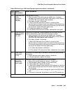
23 High-level path
Remote defect
Indicator:
HP_RDI
The far end is detecting a major problem with the signal that this
board is transmitting. The transmitted payload is invalid.
1. Make sure the ATM switch port (or a MUX port, if present
between ATM switch and the ATM-TRK board) is the same as
the ATM-TRK circuit pack’s cable interface.
2. Run test board location.
If Test #1259 fails with Error Code 23, connect a fiber
back-to-back in a looped mode (one strand of fiber connecting
the transmit transceiver to the receive transceiver of the board)
and see if the amber LED flash goes away.
● If it does the problem is off-board.
● If the amber LED continues to flash, replace the circuit pack.
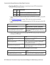
24 Loss of cell
delineation
(LCD)
On board ATM framer chip is not able to frame cells based on the
cell header.
1. Reset the board with reset board location.
2. If the error persists, replace the board.
27 SIGCON_DO
WN ATM
switch high
level signal.
The board cannot communicate with the ATM switch.
1. Busyout the board (busyout board location).
2. Test the board (test board long location).
3. If Test #1260 fails, replace the board.
4. If Test #1260 passes, make sure the ATM address on both the
S8700 Multi-Connect and the ATM switch sides are the same
for this board.
5. If the address is the same, change the port on the ATM switch
side.
6. If the error is resolved, the problem is on the ATM switch port.
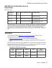
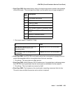
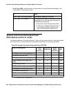
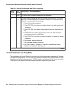
Table 209: Error type 1281 Aux Data and repair procedures (continued)
Aux
Data
Alarm
Description
Repair procedure
3 of 3