


Communication Manager Maintenance-Object Repair Procedures
538 Maintenance Procedures for Avaya Communication Manager 3.0, Media Gateways and Servers
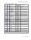
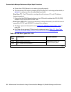
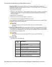
l. Error Type 1281: The loss of high-level signal indicating operational problems of equipment
located outside of the circuit pack and the fiber connected to the board. Aux Data values
are listed in Table 172: Error type 1281 Aux Data and repair procedures
on page 538.
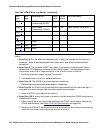
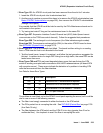
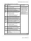
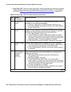
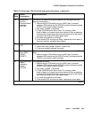
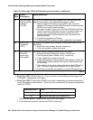
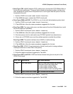
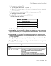
Table 172: Error type 1281 Aux Data and repair procedures
Aux
Data
Alarm
Description
Repair procedure
15 SYSCLOCK
failed
The board is not locked to the TDM backplane clock signal. This is
probably due to a Tone-Clock problem.
1. Check for TDM-BUS or TONE-BD errors in the Error Log.
2. If no other problems are present, reset the circuit pack (reset
board location)
16 Loss of Signal:
LOS
The fiber is not connected properly to the ATM-EI board or ATM
switch (or to the multiplexer section [MUX] if present).It is possible
that the board transceivers are not functioning properly.
1. Run test board location.
2. If Test #1259 fails, connect a fiber back-to-back in a looped
mode (one strand of fiber connecting the transmit transceiver to
the receive transceiver of the board) and see if the amber LED
flash goes away. If it does the problem is off-board.
3. If the amber LED continues to flash, replace the circuit pack.
17 Loss of Frame:
LOF
The fiber signal cannot obtain or maintain STM-1/OC-3 framing.
1. Try to move the fiber on the ATM switch side to a different port.
This could require administration on the ATM switch.
2. If the problem persists, reset the circuit pack (reset board
location).
18 Multiplexer
Section Alarm
Indication
Signal:
MS_AIS
There is a major problem on the far end (between multiplexer
section [MUX] and the switch) that prohibits the circuit pack from
sending a valid signal.
1. See if the ports at the MUX and/or the ATM switch are
connected snugly.
2. Run test board location.
3. If Test #1259 fails with Error Code 18, connect a fiber
back-to-back in a looped mode (one strand of fiber connecting
the transmit transceiver to the receive transceiver of the board)
and see if the amber LED flash goes away.
4. If it does, the problem is off-board.
5. If the amber LED continues to flash, replace the circuit pack; if
the error persists, escalate the problem.
1 of 3