


G700 and Media Module LEDs
Issue 1 June 2005 297
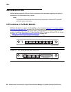
MM710 T1/E1 Media Module LEDs
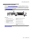
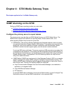
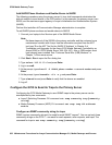
The T1/E1 Media Module has four LEDs on its faceplate (see Figure 20: T1/E1 Media Module
LEDs on page 297). Table 82: T1/E1 LEDs on page 297 shows their color and functions. The
first three are the standard LEDs, which are under software control.
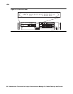
Figure 20: T1/E1 Media Module LEDs
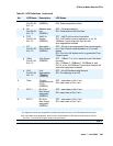
Table 82: T1/E1 LEDs
Name Color Location Description
ALM RED Top Upon power-up, this LED is turned on. Upon passing
diagnostics this LED is turned off. During normal circuit pack
operation this LED is not turned on except for certain alarm
states.
TST GREEN Second During power-up self-testing and maintenance testing
requested by the SPE, this LED is turned on.
ACT YELLOW Third This LED indicates that the clock is synchronized with a
source (usually the Central Office). The LED is blinking 2700
ms ON and 300 ms OFF. This is the most common condition.
The opposite blinking of the YELLOW LED is 300 ms ON and
2700 ms OFF. This is an error condition, and indicates that
the MM710 T1/E1 Media Module is not synchronized with a
clock.
An infrequent occurrence is a steady YELLOW LED. This
indicates in-use activity, only when clock synchronization is
set to local.
SIG GREEN Bottom This LED indicates whether the link to the Central Office (CO)
is up (equivalent to the TN464 circuit pack Status 3 GREEN
LED). See Figure 20: T1/E1 Media Module LEDs
on
page 297.
E1/T1 EIA 530A DCE
ALM
TST
ACT
SIG
EISO EMSM EOSI
mmdc710 KLC 020402