


SNC-BD (Switch Node Clock Circuit Pack)
Issue 1 June 2005 2009
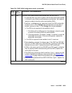
102 FAIL The SNC circuit pack cannot communicate with the SNI in slot 2.
1. If a standby SNC (one with its yellow LED off) was tested and resulted
in this error code, follow normal escalation procedures. Use status
switch-node to show the active and standby SNCs.
2. Use list configuration carrier to see if an SNI is physically
present in slot 2. If the Vintage field indicates that a circuit pack is
present, proceed to step 3. If the Vintage field shows no board:
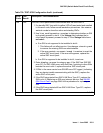
a. If an SNI is not supposed to be installed in slot 2:
1. This failure will not affect service. Use change circuit-pack
to remove the missing SNI from administration.
2. If the error persists, use reset board location to reset the
active SNC circuit pack. If the error still appears, replace the
active SNC circuit pack.
b. If an SNI is supposed to be installed in slot 2, insert one.
3. Enter display errors for category pnc. If the SNC has SNC-BD
error 513, or SNC-LINK errors with Aux Data 1 pointing to other SNIs
besides the one in slot 2, replace the active SNC circuit pack.
4. If SNIs in the same carrier have SNI-BD error 257 logged, (indicating
they are having trouble communicating with the SNC), replace the
active SNC circuit pack.
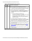
5. If the SNC being tested has SNC-LINK Error Type 1, replace the SNI
in slot 2. Replacing an SNI may interrupt service. See SNI-BD (SNI
Circuit Pack) on page 2046 for the procedure for replacing an SNI.
6. If the SNC being tested still has SNC-LINK Error Type 1, replace the
SNC circuit pack.
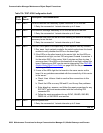
Table 739: TEST #759 Configuration Audit (continued)
Error
Code
Test
Result
Description / Recommendation
2 of 19