


Communication Manager Maintenance-Object Repair Procedures
2002 Maintenance Procedures for Avaya Communication Manager 3.0, Media Gateways and Servers
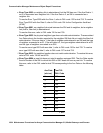
SNC LEDs
SNC circuit packs have the standard red, green, and yellow LEDs. The red and green LEDs
operate as usual: red means an alarm condition and green indicates maintenance testing in
progress. If the yellow LED is lit, this indicates that the SNC is the active circuit pack, supplying
timing to the carrier. In a duplex- or high-reliability system (unduplicated PNC), the standby SNC
in a carrier is unlit. In a critical-reliability system (duplicated PNC), an SNC in a standby switch
node carrier is lit since it is providing timing for the standby carrier.
Clear Firmware-Counters Command
SNC firmware generates error reports independently of technician-demanded tests. Therefore,
test board location clear does not affect the error status reported by firmware. The
clear firmware-counters command clears every firmware-generated error
unconditionally.
Use clear firmware-counters location to send a downlink message to the SNC circuit
pack, causing it to clear out its firmware error counters and failure database. When the firmware
failure database is cleared, the failure audit test (#777) will pass. If problems still exist, the
firmware increments its error counters and the failure audit test begins failing again.
Do not use this command instead of the repair procedures associated with the hardware error
log entries. This command may be useful if a problem was fixed but the off-board alarms
associated with the problem are still active.
Replacing SNC Circuit Packs
!
WARNING:
WARNING: Do not power down a Switch Node carrier to replace a circuit pack. Replacing an
SNC on a system with unduplicated SNCs disrupts service.
Standard-Reliability System (Unduplicated
server, PNC, and SNCs)
This procedure is destructive. Any links through the switch node carrier will go down.
1. Pull out the SNC circuit pack to be replaced.
2. Insert a new SNC circuit pack.
3. Wait for the SNC to reset. (The red and green LEDs light and then go out. The yellow LED
should be on solid.)