


Communication Manager Maintenance-Object Repair Procedures
2116 Maintenance Procedures for Avaya Communication Manager 3.0, Media Gateways and Servers
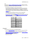
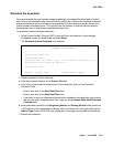
Procedure 2
If either of the two patterns described before are present, then the clock signal between active
SNC and 2 Adjacent SNIs is suspect. Proceed through the following steps until the problem is
resolved:
1. If only one SNC exists in this switch node carrier, replace the SNC. If two SNCs exist in this
switch node carrier, perform the following steps:
a. Set the standby SNC to active by executing set switch-node-clock location
with the standby SNC’s location.
b. If the problem persists, switch back to the previously active SNC using set
switch-node-clock and go to Step 2
below.
c. If the problem went away, replace the SNC that was previously active. Then set the
newly replaced SNC to active. If the problem returns, assume that the SNC that was just
replaced was not at fault and go to Step 2
below.
2. Replace the left-most SNI from the pair of adjacent SNIs.
3. Replace the right-most SNI from the pair of adjacent SNIs.
4. This could indicate a problem with the switch-node-carrier backplane.
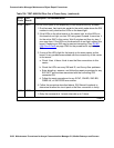
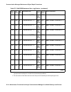
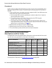
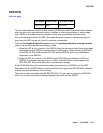
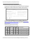
System Technician-Demanded Tests:
Descriptions and Error Codes
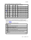
Investigate tests in the order presented below. Clearing error codes associated with the one test
may also clear errors generated from other tests in the sequence.
For descriptions of these tests, see SNI-BD (SNI Circuit Pack)
on page 2046.
Order of Investigation Short Test
Sequence
Long Test
Sequence
Reset Board
Sequence
D/ND
1
1. D = Destructive, ND = Nondestructive
Configuration audit (#759) X X ND
Failure audit (#777) X X ND
Fiber Out of Frame query (#989) X X ND
Packet Neighbor test (#767) X X ND
Circuit Path test (#755) X X ND
Destructive Facility test (#757) X D
Off-board Destructive Facility test (#756) X D
Switch Node Interface Reset test (#761) X D