


Communication Manager Maintenance-Object Repair Procedures
1050 Maintenance Procedures for Avaya Communication Manager 3.0, Media Gateways and Servers
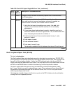
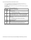
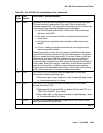
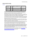
ICSU Status LEDs Test (#1227)
The TN767E DS1 circuit pack has four status LEDs on the faceplate in addition to the three
standard faceplate LEDs. These four status LEDs are associated with the 120A1 Channel
Service Unit (CSU) Module that can be connected to the TN767E board via the I/O connector
panel on the back of the port carrier.
This test is a visual test. It lights the four status LEDs red for 5 seconds, green for 5 seconds,
and yellow for 5 seconds. It then turns the LEDs off and returns control of the status LEDs to the
circuit pack.
This test runs only on TN767E
(or higher-suffixed) DS1 circuit packs administered for 24-channel
operation (1.544 Mbps).
If the 1201 CSU module/T1 sync splitter is not installed, the status LEDs are always off and this
test aborts.
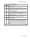
0
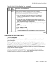
NO BOARD
The test could not relate the internal ID to the port (no board).
This could be due to incorrect translations, no board is inserted, an
incorrect board is inserted, or an insane board is inserted.
1. Verify that the board’s translations are correct. Use add ds1
location to administer the DS1 interface if it is not already
administered.
2. If board was already administered correctly, check the error log to
determine whether the board is hyperactive. If so, the board was
shut down. Reseating the board will re-initialize it.
3. If the board was found to be correctly inserted in step 1, enter
busyout board.
4. Enter reset board
5. Enter release board
6. Enter test board long
This should re-establish the link between the internal ID and the
port.
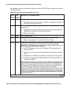
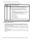
Table 360: Test #1216 End Loopback/Span Test (continued)
Error
Code
Test
Result
Description / Recommendation
3 of 3