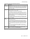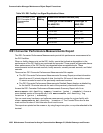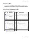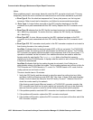
DS1-FAC (DS1 Facility)
Issue 1 June 2005 1055
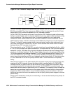
The TN574 DS1 converter has seven LEDs that provide an indication of the state of the DS1
converter circuit pack and the DS1 facilities. There is a yellow, a green, and a red LED under
software and/or firmware control. There are four Green LEDs under hardware control that
indicate, for each DS1 facility, whether a receive signal is present for the DS1 facility. From top
to bottom these green LEDs correspond to DS1 facilities A, B, C, and D respectively. If one of
the four green LED is on, it indicates a signal is present, but it does not imply that the signal is
using the correct framing format (ESF or D4) or line coding (ZCS or B8ZS). See section
DS1C-BD for the description of the red, the green, and the amber LEDs on the DS1 converter
circuit pack.
The TN1654 DS1 converter board has eleven LEDs on its faceplate. The top three system
standard LEDs (yellow, green and red) are used to provide an indication of the state of the DS1
converter board. The bottom four LEDs on the TN1654 board are labeled SPAN LEDs. These
LEDs are under firmware control. If the facility is not administered, then the LED is not lit. The
LED is lit amber if the facility is running alarm free. If the facility is detecting either a red alarm
(loss-of-signal or loss-of-frame), a yellow alarm (remote frame alarm) or a blue alarm (AIS
signal) then the LED is lit red. See section DS1C-BD for a complete description off all the LEDs.
The TN1654 DS1 converter circuit pack supports the Wideband Switching feature. The TN574
DS1 converter does not.
DS1 Facility Busyout
Busy out the MO to gracefully disconnect service. Busyout puts the object out-of-service until
the repair procedures are completed.
Use busyout ds1-facility to busy out DS1 facilities. When an attempt is made to busyout
the packet facility (or primary facility), the system prints a warning message indicating that the
override option must be used to busyout the packet facility. Busying out the packet facility
moves the packet traffic to another facility, and disconnects circuit connections on that new
facility.
The system does not allow the last packet DS1 facility to be busied out. In this case, busy out
the DS1 converter circuit pack instead.
When the busyout ds1-facility command is executed, software communicates with both
DS1 converter circuit packs in the DS1 converter complex. If the board at which the facility is
being busied out is not accessible, the abort code 2100 is returned. If the board at the other end
of the DS1 converter complex is not accessible, the abort code 105 is returned.
DS1 Facility Administration
DS1 facility administration is a part of the fiber link administration. DS1 options are set on the
Fiber Link Administration screen. For critical-reliability systems, the Fiber Link Administration
screen contains the DS1 facility options for the B side of the PNC.


