


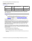
CABINET (Cabinet Sensors)
Issue 1 June 2005 765
S8700 |
8710
S8500:1
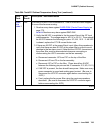
FAIL VARIABLE-SPEED FAN ASSEMBLIES: One or more fans have stopped.
If none of the fans are running:
1. Resolve every alarm against CARR-POW (Carrier Power Supply)
on
page 770.
S8700 IP Resolve every alarm against RMC-ENV.
2. Verify that 48 VDC is available to the fan power filter at the J2F local
cable connector. The voltage range is -42.5 V to -52.5 V. There should
be 48 VDC between the following pin pairs: 2/3, 8/9, 10/11. If -48 VDC
is absent, replace the CFY1B current limiter card.
3. If there are 48 VDC at the power filter’s input, follow this procedure to
verify that there are also 48 VDC at the power filter’s output to avoid
damage to the fan alarm circuit. (Note that the J2F/P2F connectors on
the power filter must be disconnected whenever connecting or
disconnecting the J2/P2 connectors on the fan assembly.
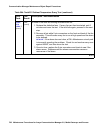
a. Disconnect connector J2F from P2F on the top of the filter.
b. Disconnect J2 from P2 on the fan assembly.
c. Reconnect J2F to P2F on the filter. (There should be 48 VDC
between the following pin pairs on the J2 connector: 2/3, 8/9, 10/11.)
d. If 48 VDC is present, the fans should have power. Make sure every
power connector is sound and making good contact. (Be sure to
disconnect the J2F/P2F connector again before reconnecting the
J2/P2.)
e. If not, replace the fan power filter using the previous procedure
described. (Be sure to disconnect the J2F/P2F connector again
before reconnecting the J2/P2.)
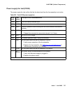
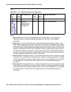
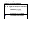
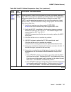
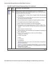
Table 264: Test #122 Cabinet Temperature Query Test (continued)
Error
Code
Test
Result
Description / Recommendation
3 of 7