


UDS1-BD (UDS1 Interface Circuit Pack)
Issue 1 June 2005 2415
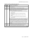
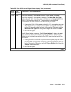
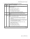
1313 FAIL The UDS1 circuit pack could not deactivate a CPE Loop-Back Jack
loopback.
1. Execute test ds1-loop location end-loopback/span-test
2. If the attempt to deactivate the CPE Loop-Back Jack is not
successful, check the cabling and investigate the problem at the CPE
Loop-Back Jack.
3. Run the test again.
1314 FAIL The UDS1 circuit pack could not deactivate a far-end CSU loopback.
4. Execute test ds1-loop location end-loopback/
span-test
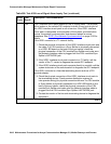
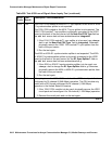
1320 FAIL Either a CSU module/Sync Splitter hardware failure or an ICSU/Sync
Splitter serial-interface audit failure was detected by the UDS1 circuit pack.
5. Replace the CSU module/Sync Splitter, and then run the test again.
6. If the test continues to fail with this Error Code, replace the UDS1-BD
circuit pack, and run the test again.
7. If the test continues to fail with this Error Code, then the problem
could be in the I/O cable between the backplane and the CSU
module/Sync Splitter.
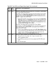
1321 FAIL DTE LOS (loss of signal) was detected between the UDS1 board and the
CSU module or the Sync Splitter. Either the UDS1 board, the CSU module/
Sync Splitter, or the I/O cable between the backplane and the CSU module/
Sync Splitter (or any combination thereof) has failed. Attempt to isolate the
problem to one of these areas.
8. Replace the CSU module/Sync Splitter, and run the test again.
9. If the test continues to fail with this Error Code, then replace the
UDS1-BD board, and run the test again.
10. If the test continues to fail with this Error Code, the problem could be
in the I/O cable between the backplane and the CSU module/Sync
Splitter.
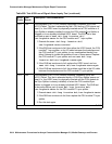
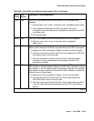
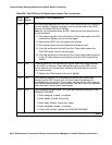
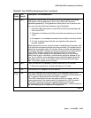
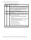
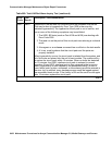
Table 858: Test #138 Loss of Signal Alarm Inquiry Test (continued)
Error
Code
Test
Result
Description / Recommendation
7 of 9