650A Power supply LEDs
Issue 1 June 2005 273
650A Power supply LEDs
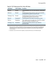
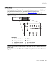
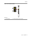
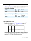
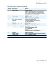
Table 70: LED and alarm conditions on page 273 shows the LED and alarm conditions for the
650A Power Supply. Ring voltage and neon bus output do not activate alarm status.
655A Power Supply LEDs
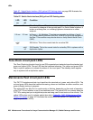
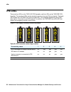
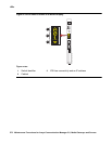
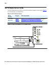
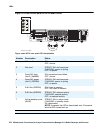
The G650 media gateway normally has two 655A power supplies. Each has a set of five LEDs,
the function of which is indicated in Table 71: 655A Power Supply LEDs
on page 273.
Normally the ring voltage LED (#5) on the left power supply is ON and the ring voltage LED on
the right power supply is OFF. This changes momentarily when the ringer interchange test is
run. The ring voltage LED will only remain lit on the right power supply when there is a power
supply failure of the left hand supply or the left hand supply is removed.
Table 70: LED and alarm conditions
Condition LED
status
Alarm
state
Fan alarm
Normal Red off;
Yellow on
Open Normal
No input power Red off;
Yellow off
Closed No input power
DC output not present (except Neon) Red on;
Yellow off
Closed DC output not present
(except Neon)
Fan alarm Red on;
Yellow on
Closed Fan alarm
Table 71: 655A Power Supply LEDs
LED Color Function
1 Red Failure of power supply or fan
2 Yellow Status of power supply OK
3 Green AC input voltage applied
4 Green DC input voltage applied
5 Green Power supply providing ring voltage


