


LEDs
294 Maintenance Procedures for Avaya Communication Manager 3.0, Media Gateways and Servers
EXT 1 LED
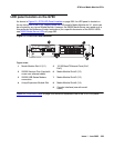
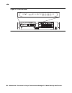
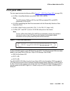
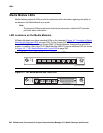
EXT 1 LED appears on the LED Panel (Figure 17: G700 Front Panel LEDs on page 291),
which reports the status of the first 10/100 MB/sec port (these LEDs report the 8 different
functional statuses dictated by the left and right arrow buttons).
EXT 2 LED
EXT 2 LED appears on the LED Panel (Figure 17: G700 Front Panel LEDs on page 291),
which reports the status of the second 10/100 MB/sec port (these LEDs report the 8 different
functional statuses dictated by the left and right arrow buttons).
G700 LED panel definitions
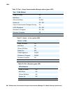
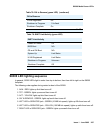
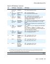
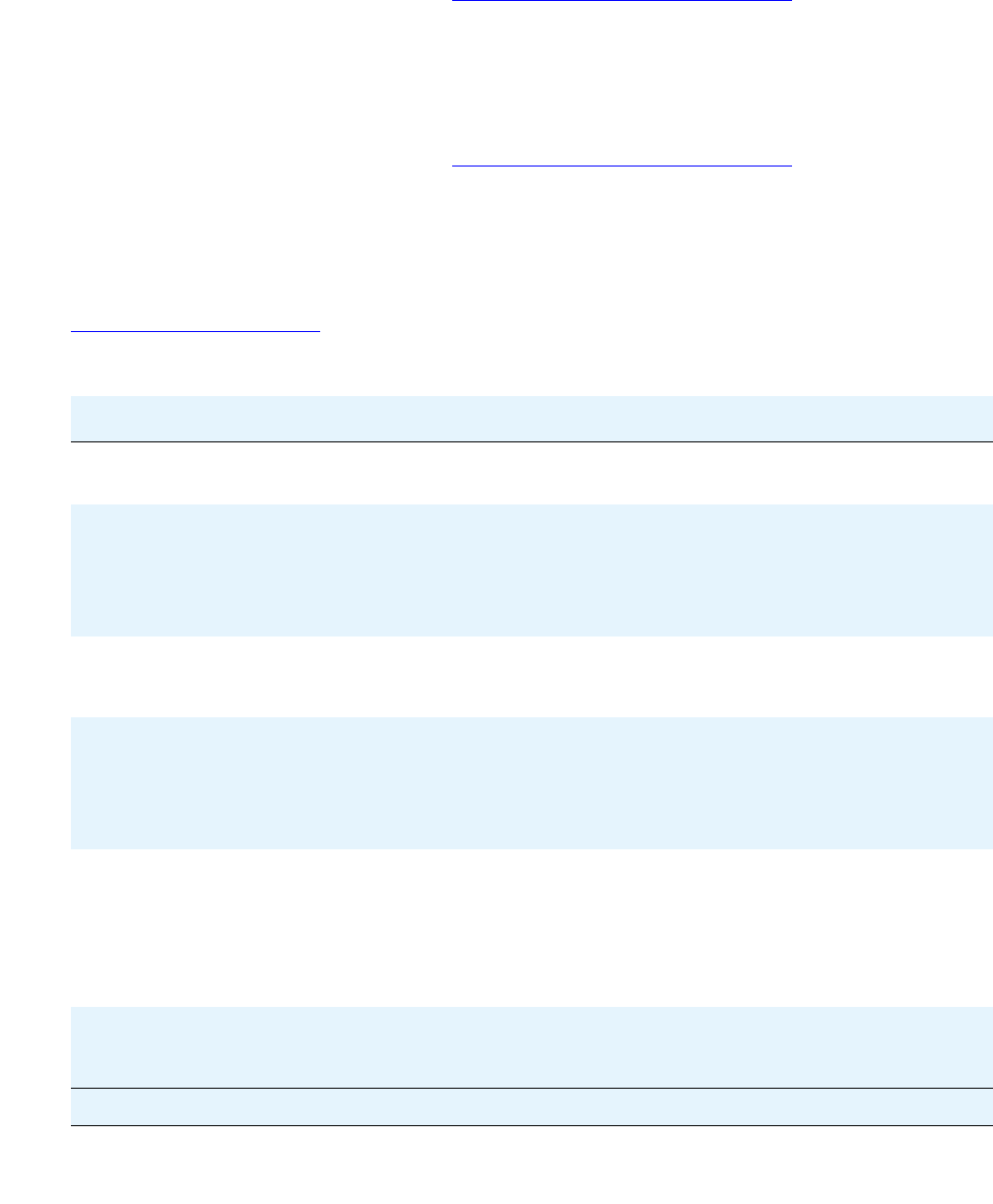
Table 81: LED Definitions on page 294 illustrates the LED definitions for the G700 LED Panel.
Table 81: LED Definitions
No. LED Name Description LED States
1 ALM Alarm Status
Color is RED
OFF - No alarms exist
ON (RED) - Alarm exists on the chassis itself
2 PWR Alarm Status
Color is
GREEN
OFF - Power is down
ON - Power is up
Blinking - every 1.2 seconds (400ms on, 800ms off)
when 5 volts power is not available to the riser
board and the Media Modules
3 CPU CPU Operation
Color is
GREEN
OFF - CPU is in boot operation or is running BIST
ON - CPU boot operation and BIST completed
4 MSTR Master/Slave
Status Color is
GREEN
OFF - Slave box of the stack
ON - Master of the stack and redundant cable is not
present or not active
1 Blink every 1.5 sec - Master of the stack and
active redundant cable
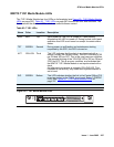
5 a LNK port
51-66, Ext
1-2
Port Status
Color is
GREEN
OFF - Port disabled or not existent. At phase 1, or
link fail of Giga ports.
ON - Port is enabled and link is OK.
1 Blink every 1.5 sec - Link test fail (of 10/100M
ports only at phase 1)
2 Blinks every 1.5 sec - Partition
b COL
Port 51-66,
Ext 1-2
Collision
(GREEN)
OFF - No collision or FDX port
ON - Collision occurred on line
1 of 2