


ATM-TRK (Circuit Emulation Service Circuit Pack)
Issue 1 June 2005 623
h. Error Type 771: the ATM switch is sending cells with unknown Virtual Path-Identifier (VPI)
and Virtual Channel-Identifier (VCI) addresses.
1. Make sure that the ATM-TRK circuit-pack address is administered identically on the ATM
switch and the S8700 Multi-Connect system.
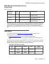
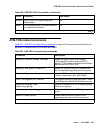
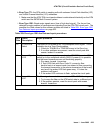
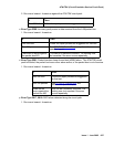
i. Error Type 1281: Board major signals error (loss of high-level signal). The far end has
detected a major problem in transmissions originating from the ATM-TRK circuit pack. The
possible Aux Data values for this software counter are listed in Table 209: Error type 1281
Aux Data and repair procedures on page 623.
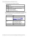
Table 209: Error type 1281 Aux Data and repair procedures
Aux
Data
Alarm
Description
Repair procedure
15 SYSCLOCK
failed
The board is not locked to the TDM backplane clock signal. This is
probably due to a Tone-Clock problem.
1. Check for TDM-BUS or TONE-BD errors in the Error Log.
2. If no other problems are present, reset the circuit pack with
reset board location
16 Loss of Signal:
LOS
The fiber is not connected properly to the ATM-TRK board or ATM
switch (or to the multiplexer section [MUX] if present).It is possible
that the board transceivers are not functioning properly.
1. Run test board location.
2. If Test #1259 fails with Error Code 16, connect a fiber
back-to-back in a looped mode (one strand of fiber connecting
the transmit transceiver to the receive transceiver of the board)
and see if the amber LED flash goes away. If it does the
problem is off-board.
3. If the amber LED continues to flash, replace the circuit pack.
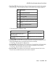
17 Loss of Frame:
LOF
The fiber signal cannot obtain or maintain STM-1/OC-3 framing.
1. Try to more the fiber on the ATM switch side to a different port.
2. If the problem persists, reset the circuit pack with reset
board location.
1 of 3