


Communication Manager Maintenance-Object Repair Procedures
2046 Maintenance Procedures for Avaya Communication Manager 3.0, Media Gateways and Servers
SNI-BD (SNI Circuit Pack)
S8700 MC
The TN573 Switch Node Interface (SNI) circuit pack is part of the Center Stage Switch (CSS)
configuration. It resides in a switch node carrier that alone or with other switch nodes make up a
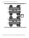
CSS. SNIs connect to other SNIs or Expansion Interface (EI) circuit packs via fiber links.
SNI-to-EI fiber links are used to connect port networks to a switch node carrier and SNI-to-SNI
fiber links are used as inter-switch node fibers. In critical-reliability systems, the fiber link
connections are duplicated as part of port-network connectivity (PNC) duplication. In standard-
and high-reliability systems, the PNC is not duplicated.
There may be up to 16 SNIs in a switch node carrier. They are located in slots 2 through 9 and
slots 13 through 20. Slot 11 in a switch node carrier is not used. One or two TN572 boards
(SNCs) must reside in switch node carrier positions 10 and 12. The SNIs connect to other SNIs
in the same carrier via the backplane; these connections within the same carrier are referred to
as peer-links. Each SNI also connects via an optical fiber or metallic connection to another SNI
in another carrier or to an EI in a port network (PN). These connections are referred to as fiber
links.
The Switch Node Clock (SNC) provides timing for the SNIs in the entire carrier. When two SNCs
reside in the same switch node carrier, one is in active mode and one is in standby mode. The
yellow LED on the active SNC will be on solid. The yellow LED on the standby SNC will be off.
See SYNC (Port-Network Synchronization)
on page 2143 for an explanation of how SNIs are
involved in timing synchronization.
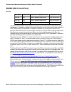
Figure 118: CSS Configuration with Unduplicated PNC and 1 Switch Node Carrier
on
page 2047 shows an unduplicated CSS with one switch node. A single switch node can
accommodate up to 16 port networks. A system with two switch nodes can accommodate up to
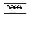
22 port networks. Figure 119: CSS Configuration with Duplicated PNC and 4 Switch Node
Carriers on page 2048 shows a two-switch node CSS with duplicated PNC (four switch node
carriers). In this configuration, each PNC (A and B) contains two switch nodes. The cabinet
numbers for the switch node carriers are typical cabinet numbers. The PNs on the top half of the
figure (PNC A) are the same as the PNs on the bottom half of the figure (PNC B).
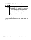
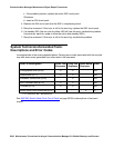
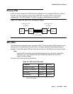
MO Name Alarm Level Initial SAT Command to Run Full Name of MO
SNI-BD MAJ test board location s SNI Circuit Pack
SNI-BD MIN test board location s SNI Circuit Pack
SNI-BD WRN test board location s SNI Circuit Pack