


LEDs
264 Maintenance Procedures for Avaya Communication Manager 3.0, Media Gateways and Servers
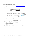
The yellow LED under firmware control is used to indicate the state of the physical fiber
interface, the Fiber Channel (link to EI or SNI), the DS1 Control Channel (link to opposite
DS1CONV board), and the S8700 Media Server communications link in the following manner
and order of priority. (The yellow LED remains on for longer periods of time as the DS1CONV
complex becomes closer to being fully operational.)
1. If the fiber is Out of Frame or if a Fiber Loss of Signal condition exists, the yellow LED will
flicker at a 5 Hz rate (on for 100 mS, off for 100 mS).
2. If the fiber channel is down (DS1 Converter circuit pack/fiber endpoint communications), the
yellow LED will flash at a 1 Hz rate (on for 500 ms, off for 500 ms).
3. If the DS1 control channel is down between the two DS1CONVs in the DS1CONV complex,
the yellow LED will pulse at a 0.5 Hz rate (on for 1 second, off for 1 second).
4. If the S8700 Media Server communications link is down, the yellow LED will wink off every 2
seconds for 200ms (2 sec on, 200 msec off).
5. If all is well with the fiber interface and every communications channel, the yellow LED will
remain on continuously in a standard- or high-reliability system configuration. In
critical-reliability systems (duplicated PNC), an active DS1CONV circuit pack will have its
yellow LED on continuously, and a standby DS1CONV circuit pack will have its yellow LED
off. The LED will then be under software control.
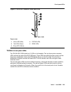
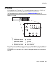
The bottom four green LEDs on the TN574 DS1CONV board are under hardware control. The
four green LEDs indicate, for each DS1CONV facility, whether a receive signal is present for the
DS1 facility
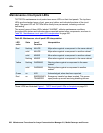
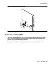
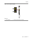
The next four LEDs on the TN1654 DS1CONV board are labeled STATUS LEDs and are for
future use. These LEDs will not be lit.
The bottom four LEDs on the TN1654 board are labeled SPAN LEDs. These LEDs are under
firmware control. If the facility is not administered, then the LED is not lit. The LED is lit amber if
the facility is running alarm free. If the facility is detecting either a red alarm (loss-of-signal or
loss-of-frame), a yellow alarm (remote frame alarm) or a blue alarm (AIS signal) then the LED is
lit red. The SPAN SELECT switch on the TN1654 faceplate is for future use. Pushing the switch
will have no effect on the board. See Figure 3: TN1654 DS1CONV circuit pack
on page 265 for
a view of the faceplate on the TN1654 DS1CONV circuit pack.