


Communication Manager Maintenance-Object Repair Procedures
2412 Maintenance Procedures for Avaya Communication Manager 3.0, Media Gateways and Servers
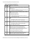
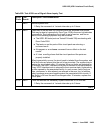
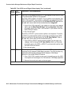
1301 FAIL The 120A1 CSU module or the 401A T1 sync splitter, or the 402A or 403A
E1 synchronization splitter is not expected.
The 120A1 CSU module or the 401A T1 sync splitter is not expected: The
120A1 CSU module/T1 sync splitter is physically connected to the UDS1
board on the back of the port carrier, but the Near-End CSU Type field on
the add ds1 screen has not been administered as integrated.
1. If the 120A1 CSU module/T1 sync splitter is to be used, use change
ds1 to set the Near-End CSU Type field to integrated. Otherwise,
physically remove the 120A1 CSU module/T1 sync splitter from the
back of the port carrier.
2. Run the test again.
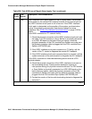
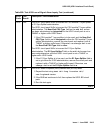
The 402A or 403A E1 synchronization splitter is not expected: The 402A
or 403A E1 synchronization splitter is physically connected to the UDS1
board on the back of the port carrier, but the E1 Sync-Splitter? field on
the add ds1 screen has not been administered as y.
1. If the 402A or 403A E1 synchronization splitter is to be used, use
change ds1 to change the E1 Sync-Splitter field to y. Otherwise,
physically remove the 402A or 403A E1 synchronization splitter from
the back of the port carrier.
2. Run the test again.
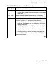
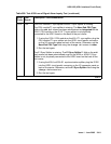
1302 FAIL Attempting to use the 120A1 CSU module with a UDS1 circuit pack that is
configured for 32-channel (2.048-Mbps) operation. The CSU module only
works with a DS1 board configured for 24-channel (1.544-Mbps)
operation in the United States of America.
1. If the 120A1 CSU module is to be used, physically remove the UDS1
circuit pack and reconfigure it for 24-channel (1.544-Mbps) operation.
2. Reinsert the circuit pack and run the test again.
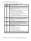
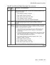
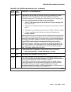
Table 858: Test #138 Loss of Signal Alarm Inquiry Test (continued)
Error
Code
Test
Result
Description / Recommendation
4 of 9