LEDs
268 Maintenance Procedures for Avaya Communication Manager 3.0, Media Gateways and Servers
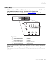
Avaya Ethernet Switch LEDs
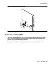
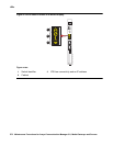
The Avaya Ethernet switch’s LEDs are shown in Figure 4: Avaya Ethernet switch LEDs on
page 268.
Figure 4: Avaya Ethernet switch LEDs
The following three LEDs are the primary indicators:
● SYS shows whether this module is the Cajun P330 stack master.
● OPR shows CPU boot status.
● PWR shows when power is on.
For all other LEDs, refer to the quick start guide and user guide that came with the Avaya
Ethernet switch.
Figure notes:
1.
Ports in use
3.
Power
2.
CPU boot status
4.
Lights if this module is the Cajun
P33x stack master
1
13
2
14
LAG
3
15
4
16
9
21
10
22
LAG
11
23
12
24
CONSOLE
5
17
6
18
LAG
7
19
8
20
51
EXPANSION
SLOT
59
FIV
55
63
LNK
OPRSYS
PWR
COL
TxRx
FC
Hspd
LAG
FDX
1
13
5
17
9
21
52
60
56
64
2
14
6
18
10
22
53
61
57
65
3
15
7
19
11
23
54
62
58
66
4
16
8
20
12
24
Cajun P333T Switch
51
EXPANSION
SLOT
59
FIV
55
63
LNK
OPRSYS
PWR
COL
Tx Rx
FC
Hspd
LAG
FDX
1
13
5
17
9
21
52
60
56
64
2
14
6
18
10
22
53
61
57
65
3
15
7
19
11
23
54
62
58
66
4
16
8
20
12
24
ledl333t KLC 030602
1
3
2
4


