


FSN Series • User’s Guide • Rev 01 99
3. Control Panel Orientation
Control Panel Rear
`çåíêçä=m~åÉä=oÉ~ê=
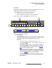
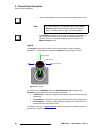
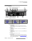
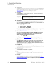
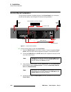
The figure below illustrates the rear of the control panel:
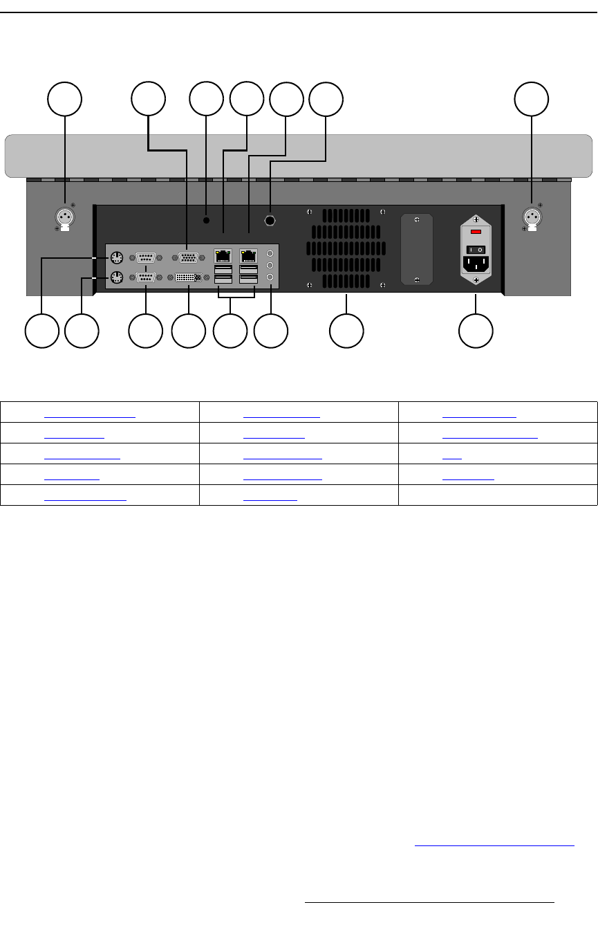
Figure 3-24. Control Panel Rear
Following are descriptions of each rear panel connector:
1) Light Connectors
One XLR Connector is provided on each side of the rear panel for the low-
voltage “script” lights. The knob marked “Light” on the top of the control panel
adjusts the brightness.
2) Mouse Port
The Mouse Port is not supported. If required, use an available USB port for a
mouse connection.
3) Keyboard Port
The Keyboard Port is not supported. If required, use an available USB port for a
keyboard connection.
4) Com Ports
The two 9-pin D Com connectors are not used.
5) VGA Connector
One 15-pin D VGA connector is provided for the control panel’s analog output.
The output enables you to view the menu system on an external non-touch screen
monitor, if required. In Appendix A, refer to the “Analog 15-pin D Connector
”
section on page 439 for pinout details.
100 - 240 VAC
50 - 60 Hz
2.3A
12V DC OUT 1.5A
CPU
Ethernet
Port 1
Ethernet
Port 2
Light Light
1 1
2 4 10 143 6 12
5 7 8 9 11
13
1) Light Connectors 6) DVI Connector 11) DC Power Out
2) Mouse Port 7) CPU Switch 12) Audio Connectors
3) Keyboard Port 8) Ethernet Port 1 13) Fan
4) Com Ports 9) Ethernet Port 2 14) AC Power
5) VGA Connector 10) USB Ports