


FSN Series • User’s Guide • Rev 01 81
3. Control Panel Orientation
Control Panel Descriptions
jLb=_~åâ
An M/E bank is essentially a video layer which, in combination with other switcher banks,
enables you to create the overall “look” of your program. Please note:
• Three buses are provided for selecting sources: BG, PST and KEY.
• Sources are the same in each vertical column of buttons. For example, if CAM 2
is mapped to button 2, CAM 2 appears on button 2 on all switcher buses.
• The M/E bank has an associated M/E Transition Section to the right. In this
section, you set up “effects” and transitions using the sources selected in the M/E.
• Using the Memory/Transition Section, you can store all or part of an M/E bank.
• An M/E bank provides tally indications. In Chapter 7, refer to the
“Understanding Tally” section for details.
• An M/E bank operates in “flip-flop” mode. In Chapter 7, refer to the
“Understanding Flip-flop Mode” section on page 314 for details.
• Button color has important significance. In Chapter 7, refer to the
“Understanding Button Color” section on page 311 for details.
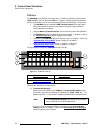
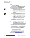
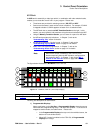
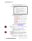
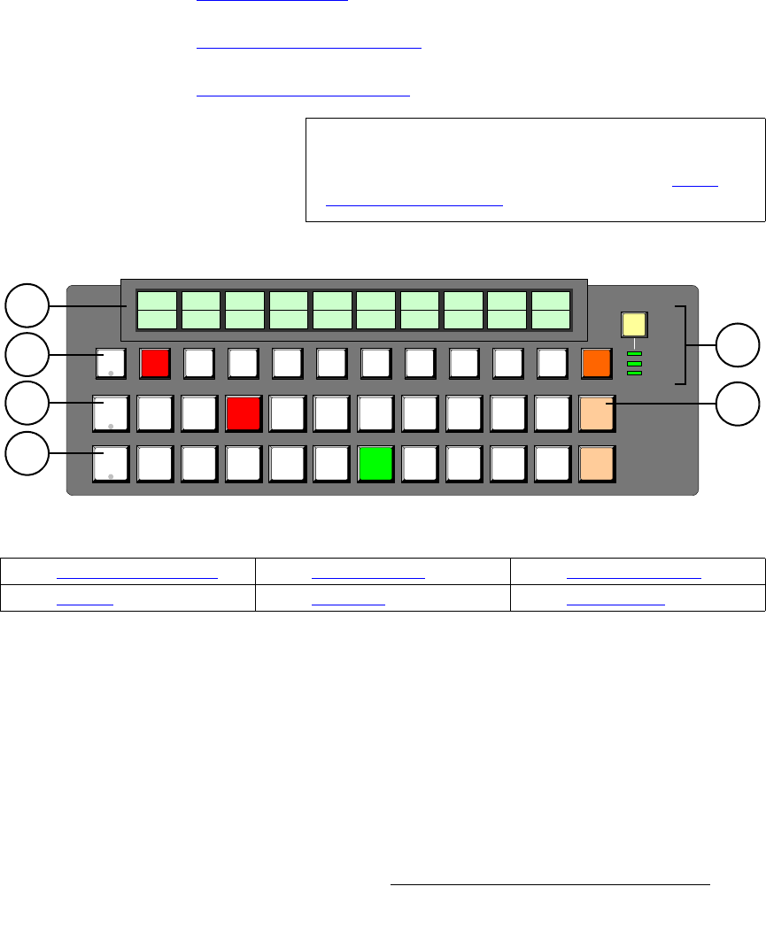
The figure below illustrates the M/E Bank on the FSN-150.
Figure 3-11. M/E Bank, FSN-150 (with sample displays)
Following are descriptions of each section:
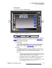
1) Programmable Displays
Above each button on the Key Bus, a Programmable Display shows the source
names that are assigned during setup. The labels are dynamic — if the source is
mapped to another button, the label follows. Please note:
~ In the Programmable Displays, the top row is the unshifted source, the
bottom row is the shifted source.
~ When M/E 2 control is enabled on the FSN-150, all Programmable
Displays turn orange.
Note
When M/E 2 control is enabled on the FSN-150, M/E 1
buttons temporarily become M/E 2 buttons, and operations
are identical to M/E 1. In Chapter 7, refer to the “M/E 2
Control on the FSN-150” section on page 349 for details.
K
E
Y
B
G
P
S
T
KEY 1
KEY 2
CUSTOM
SEL
M/E
BLACK
SHIFT
BLACK
SHIFT
BLACK SHIFT
CAM1
GFX1
CAM2
GFX2
CAM3
VTR1
VTR3
VTR2
DVD1
DVD2
PC1
PC3
PC2
STL1
COL1
STL2
COL2
3
4
2
1
5
6
1) Programmable Displays 3) Background Bus 5) Key Control Section
2) Key Bus 4) Preset Bus 6) SHIFT Buttons