


56 FSN Series • User’s Guide • Rev 01
2. FSN-1400 Orientation
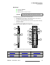
Card Descriptions
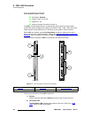
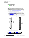
2) Card Power LED
The Card Power LED indicates power status for the card. Refer to the “Card
LEDs” section on page 64 for details.
3) Loaded LED
The Loaded LED indicates the status of all FPGAs on the card. Refer to the
“Card LEDs” section on page 64 for details.
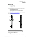
4) Universal Input 1
Three connectors are provided for Universal Input 1 (1 x HD15, 1 x DVI-I, 1 x
BNC). Using these connectors, different combinations of inputs can be connected
to the FSN-1400, as outlined below, but only one of the three connectors can be
used at a time on the control panel.
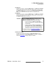
Cells with check marks denote the connections required for the indicated format.
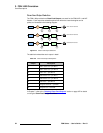
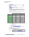
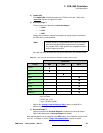
* up to 165 MHz
** NTSC, PAL or HD
*** up to 165 MHz (UXGA)
Please note the following important points regarding the UIC:
~ Refer to the “Analog Format Connection Table” section on page 65 for
additional information on using the HD-15 connector.
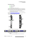
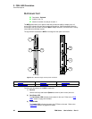
5) Universal Input 2
Input connections for Universal Input 2 are identical to Universal Input 1. Refer
to the explanation of Universal Input 1 for details.
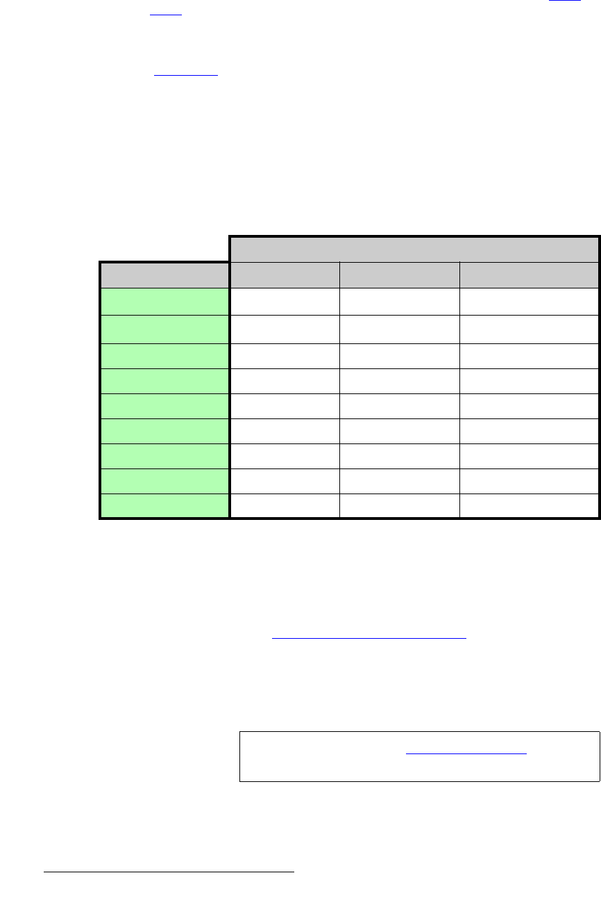
Table 2-6. UIC connector combinations for selected universal input formats
Connectors
Format BNC DVI-I HD-15
HD-SDI
SD-SDI
DVI *
CVBS
Y/C
YPbPr **
RGsB
RGBS
RGBHV ***
Note
In Appendix A, refer to the “Delay Specifications” section on
page 438 for details on UIC delay.