


FSN Series • User’s Guide • Rev 01 313
7. Operations
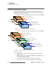
Understanding Switcher Layers
• M/E 2 provides a “re-entry” output that flows into the PGM bank.
• Please note:
~ On each M/E, the BG and PST buses comprise the background layer —
the farthest layer upstream, and visually, the layer that’s behind Key 1
and Key 2.
~ Key 1 is downstream of the BG and PST layer, but upstream of Key 2.
Keys created on Key 1 are visually “over” the BG and PST layer, but
“under” Key 2.
~ Key 2 is the farthest layer downstream on an M/E. Keys created on Key
2 are visually “over” BG, PST and Key 1.
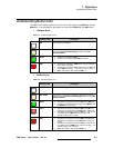
~ Even if you swap key settings by pressing the {Swap Key Settings}
button, the priority of the layers does not change.
• The PGM bank consist of Program (PGM) and Preset (PST) buses, and a single
layer of keying (DSK). The bank provides Program, Preview and Clean Feed
outputs. Please note:
~ The entire PGM bank is downstream of M/E 1 and M/E 2 — visually on
top of all effects created on the M/Es.
~ The PGM and PST buses comprise the bank’s background layer — the
farthest layer upstream in the bank, and visually, the layer that’s behind
the DSK.
~ The DSK is downstream of the PGM and PST layer, but upstream of the
FTB (fade to black) function. Keys created on the DSK are visually
“over” PGM and PST.
~ FTB is the farthest function downstream in the switcher. This function
enables you to fade the entire switcher (including DSK) to black
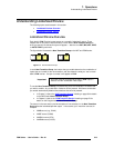
• In the default “priority” layering of the switcher when M/E 2 control is enabled, the
M/E 1 bank is upstream of M/E 2, and M/E 2 is upstream of PGM. Thus, M/E 1 is
visually behind, M/E 2 is in the middle, and PGM is visually on top.
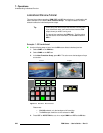
However, using the
Other Setup Menu (located on the main System Menu) you
can change the priority of the two M/E banks using the
{M/E Order} function. In
Chapter 5, refer to the “
Other Setup Menu” section on page 253 for details.