


112 FSN Series • User’s Guide • Rev 01
4. Installation
FSN-1400 System Connections
cpkJNQMM=póëíÉã=`çååÉÅíáçåë
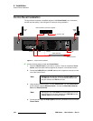
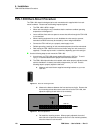
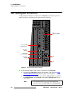
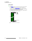
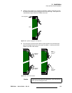
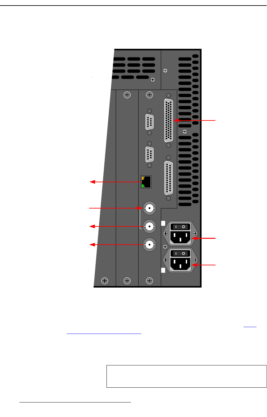
The figure below illustrates the connections on the System card’s rear panel, plus the
power connections. Use this figure for reference during installation.
Figure 4-9. System card and power connections
Use the following steps to install “system” connections on the FSN-1400:
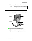
1. Ensure that the FSN-1400 is properly rack mounted. If not, refer to the “FSN-
1400 Rack-Mount Procedure” section on page 110 for instructions.
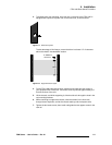
2. On the System card’s rear panel, ensure that the Ethernet Port is connected to
the Ethernet Switch, and the Switch is connected to Ethernet Port 1 on the
control panel.
12 13 14
GPIO
Tally
Ref In
Loop
Ref Out
Ethernet
Serial 2
Serial 1
100 - 240 VAC
8A, 50 - 60 Hz x2
2
1
To
Tally “Y” Adapter
AC
AC
Reference
Video In
Reference
Video Loop Out
To
Control Panel’s
Ethernet Port 1
Reference
Output
Note
As an alternate method, you can use a direct Ethernet
connection between the FSN-1400 and the Control Panel.