


312 FSN Series • User’s Guide • Rev 01
7. Operations
Understanding Switcher Layers
råÇÉêëí~åÇáåÖ=pïáíÅÜÉê=i~óÉêë
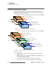
To help you understand FSN Series architecture from a production perspective, and to
assist with the creation of switcher “looks,” the diagram below illustrates how the various
switcher banks are layered on the FSN-150.
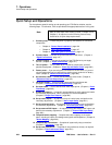
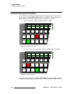
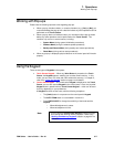
• M/E 2 Off — The diagram below shows layering when M/E 2 control is disabled:
Figure 7-1. Switcher layers, FSN-150 — M/E 2 control disabled
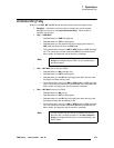
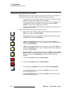
• M/E 2 On — The diagram below shows layering when M/E 2 control is enabled:
Figure 7-2. Switcher layers, FSN-150 — M/E 2 control enabled
The following rules apply:
• Input video from the FSN-1400 flows into the M/E and PGM banks across the
crosspoint matrix.
• Both M/E 1 and M/E 2 consist of Background (BG) and Preset (PST) buses, and
two layers of keys (
Key 1 and Key 2).
• Each M/E bank provides Program, Preview and Clean Feed outputs.
• M/E 1 provides a “re-entry” output that flows into M/E 2 and the PGM bank.
M/E 1
PGM
Key 1
Key 2
DSK
FTB
BG and PST buses
PGM and PST buses
M/E 1 Clean 1 (Pre Key 1)
M/E 1 Clean 2 (Pre Key 2)
M/E 1 Out
PGM Clean 1 (Pre DSK)
Program Out (Post FTB)
PGM Clean 2 (Post FTB)
Re-entry
Input Video
M/E 1
Key 1
Key 2
BG and PST buses
M/E 1 Clean 1 (Pre Key 1)
M/E 1 Clean 2 (Pre Key 2)
M/E 1 Out
M/E 2
PGM
Key 1
Key 2
DSK
FTB
Input Video
BG and PST buses
PGM and PST buses
M/E 2 Clean 1 (Pre Key 1)
M/E 2 Clean 2 (Pre Key 2)
M/E 2 Out
PGM Clean 1 (Pre DSK)
Program Out (Post FTB)
PGM Clean 2 (Post FTB)
Re-entry
Re-entry