


FSN Series • User’s Guide • Rev 01 41
2. FSN-1400 Orientation
Hardware Description
`Ü~ëëáë=oÉ~ê
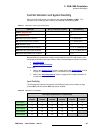
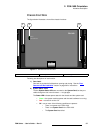
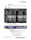
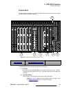
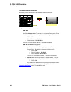
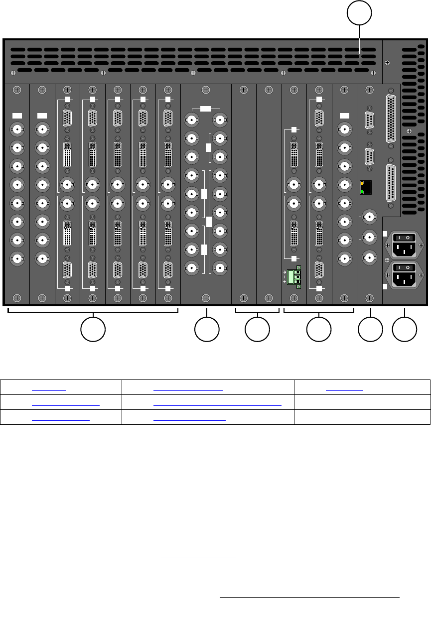
The figure below illustrates a rear view of the FSN Series chassis, with all slots fully loaded
with both required and optional panels:
Figure 2-3. Sample FSN Series chassis, rear view
In the descriptions below, slots are numbered from left to right:
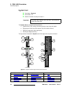
1) Air Vents
At the top of the chassis, Air Vents are provided to assist with cooling. Air flows
from the front of the chassis to the rear. To prevent overheating, do not block the
air vents.
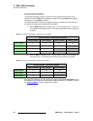
2) Input Card Panels
Slots 1 through 7 are reserved for two types of input card panels:
~ NIC panels. Up to four panels can be installed in slots 1 through 4. See
the “Native Input Card
” section on page 53 for details.
Slot: 1234567 8 910111213 14
1
2
3
4
5
6
7
8
SDI
1
2
3
4
5
6
7
8
SDI
1
2
3
4
5
6
7
8
SDI
2
CLN
Fill
PVW
PVW
PGM
CLN
1
PGM
CLN
3
4
5
6
M/E 2
CutPVW
M/E 1
AUX
DSK
PGM
GPIO
Tally
Ref In
Loop
Ref Out
Ethernet
Serial 2
Serial 1
100 - 240 VAC
8A, 50 - 60 Hz x2
2
1
SDI
AnalogDVI Digital
Analog DVI Digital
2
1
SDI
AnalogDVI Digital
Analog DVI Digital
2
1
SDI
AnalogDVI Digital
Analog DVI Digital
2
1
SDI
AnalogDVI Digital
Analog DVI Digital
2
1
SDI
AnalogDVI Digital
Analog DVI Digital
2
1
SDI
AnalogDVI Digital
Analog DVI Digital
2
1
SDI
DVI Digital
DVI Digital
2
1
LTC Input
1
62 43 5 7
1) Air Vents 4) DVE (Blank) Panel 7) AC Power
2) Input Card Panels 5) Aux and MVR Output Card Panels
3) M/E Card Panel 6) System Card Panel