76 FSN Series • User’s Guide • Rev 01
3. Control Panel Orientation
Control Panel Descriptions
mdj=qê~åëáíáçå=pÉÅíáçå
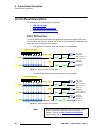
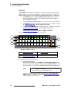
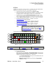
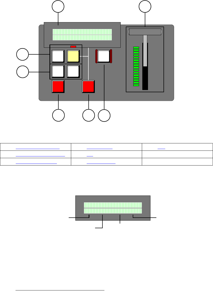
The PGM Transition Section provides controls for creating the switcher’s primary output,
using cuts, mixes, wipes, a downstream key and a downstream “fade to black.” The figure
below shows the PGM Transition Section:
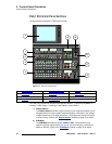
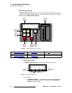
Figure 3-6. PGM Transition Section (sample)
Following are descriptions of each section:
1) PGM Transition Display
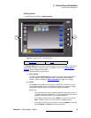
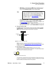
The PGM Transition Display provides the four important status labels:
Figure 3-7. PGM Transition Display
From left to right:
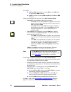
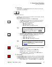
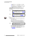
~ Last Memory Register — indicates the last memory register recalled to
the PGM bank. When you recall another register using the Memory
Section, the register updates.
PGM / PST TRANSITION
BG
MIX
FTB
M E M D S K T R A N F T B
6 5 P C 2 3 0 6 0
WIPE
CUT
AUTO
TRAN
DSK
5
1
6
3
4
7
2
1) PGM Transition Display 4) Effects Group 7) FTB
2) T-Bar and Transition LEDs 5) Cut
3) Next Transition Group 6) Auto Transition
M E M D S K T R A N F T B
6 5 P C 2 3 0 6 0
Last
Memory
Register
DSK
Source
Current
Transition Rate
Current
Fade to Black
Rate


