FSN Series • User’s Guide • Rev 01 293
6. System Setup
Universal Input Setup
råáîÉêë~ä=fåéìí=pÉíìé
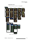
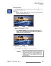
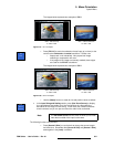
FSN Series system setup: Step 10
In this procedure, you will perform a complete setup on all universal switcher inputs.
Ensure that your inputs are properly connected to the selected
UIC before continuing.
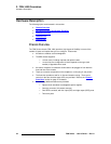
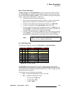
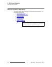
S Prerequisite — Ensure that you are familiar with the following menus:
~ Input Menu — Chapter 5, “Input Menu,” page 202.
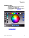
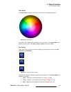
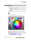
~ Connector Colors — Chapter 5, “Connector Colors,” page 204.
~ Input Setup Menu (Universal Inputs) — Chapter 5, “Input Setup Menu
for Universal Inputs,” page 214.
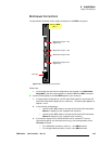
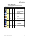
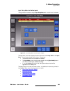
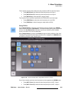
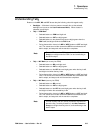
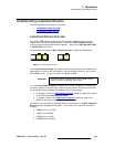
Universal Input Setup — Use the following steps for basic universal input setup:
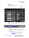
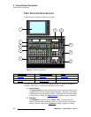
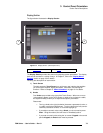
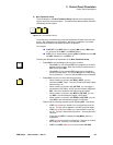
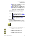
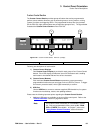
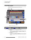
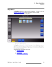
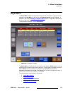
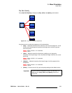
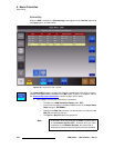
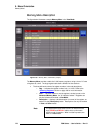
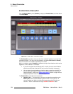
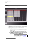
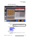
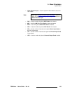
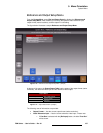
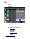
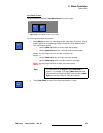
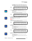
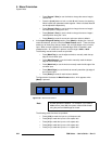
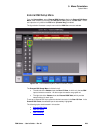
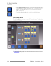
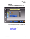
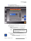
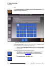
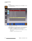
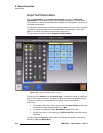
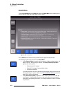
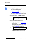
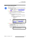
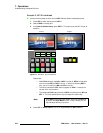
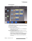
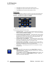
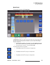
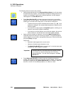
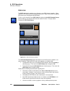
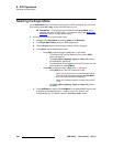
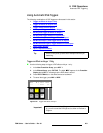
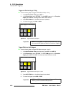
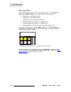
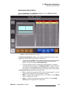
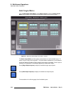
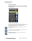
1. In the Menu Bar, press {System} to access the System Menu.
2. Press {Input Setup} to display the Input Menu.
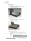
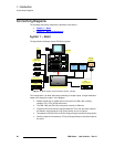
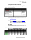
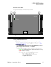
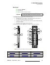
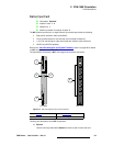
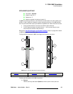
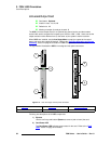
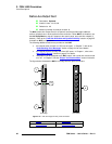
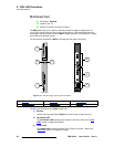
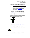
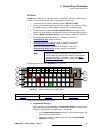
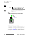
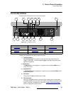
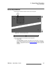
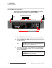
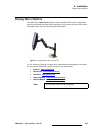
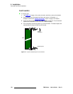
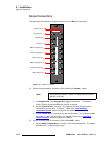
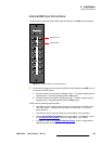
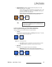
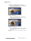
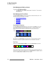
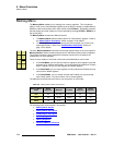
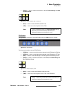
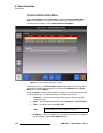
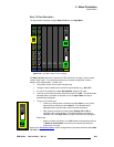
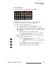
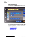
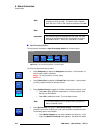
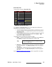
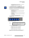
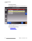
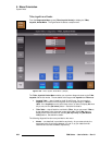
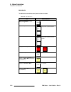
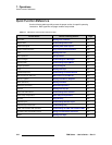
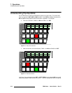
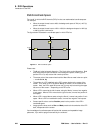
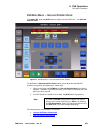
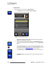
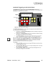
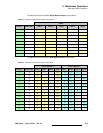
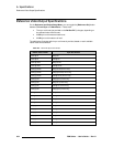
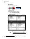
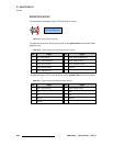
3. In the Rear I/O View, press the input connector on the UIC that you want to set
up. A yellow highlight is placed around all three input connectors, and in the
Input
Table
, the input is highlighted.
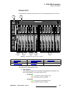
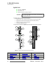
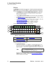
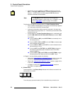
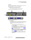
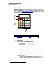
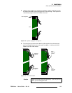
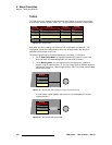
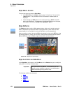
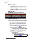
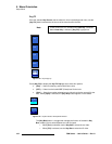
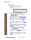
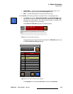
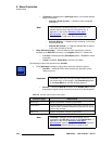
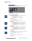
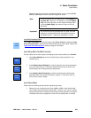
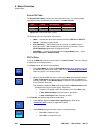
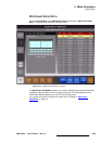
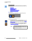
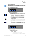
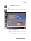
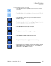
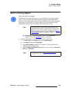
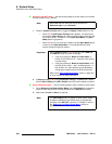
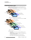
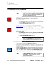
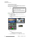
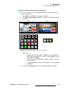
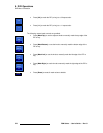
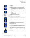
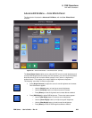
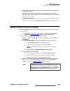
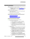
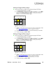
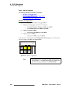
4. Select the individual UIC connector — either the BNC, HD-15 or DVI. A green
highlight indicates the selection.
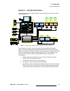
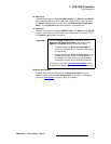
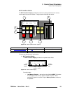
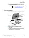
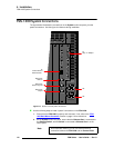
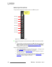
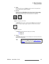
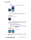
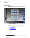
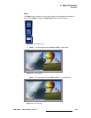
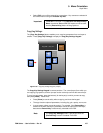
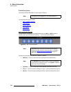
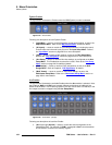
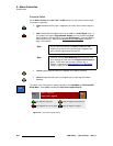
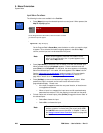
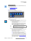
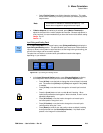
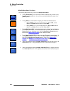
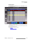
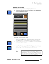
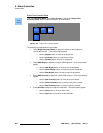
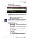
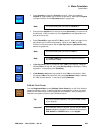
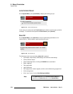
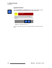
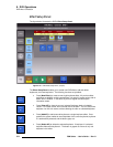
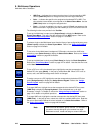
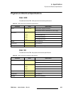
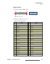
5. Press {Map to} to map the selected input to the control panel, or re-map it to
another button. When the
Map To Pop-up appears, on the Program Bank’s
Preset Bus, press the button on which you want the input to appear.
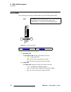
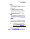
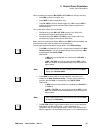
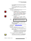
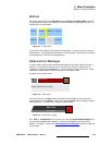
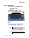
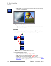
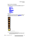
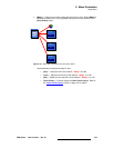
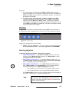
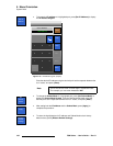
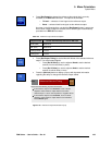
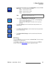
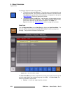
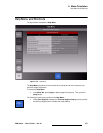
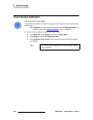
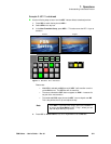
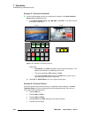
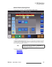
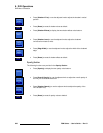
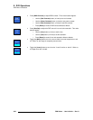
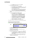
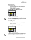
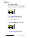
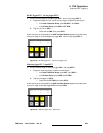
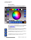
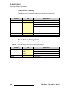
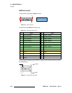
6. Press {Input Name} to name (or re-name) the selected input. When the pop-up
Keyboard appears, enter the desired name and press {Enter} on the Keyboard.
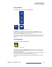
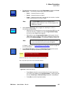
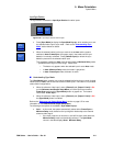
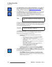
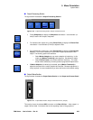
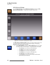
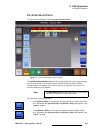
7. If required, press {Un-map} to remove the selected input from the panel. Note
that the name and all associated setup parameters are retained.
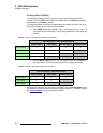
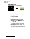
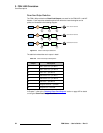
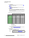
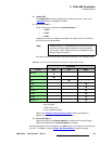
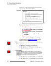
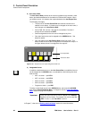
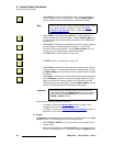
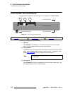
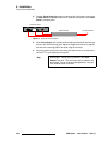
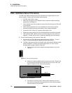
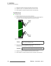
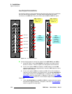
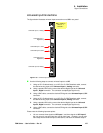
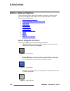
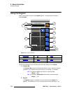
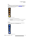
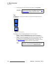
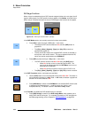
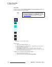
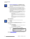
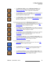
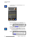
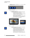
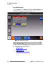
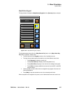
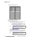
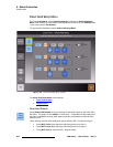
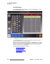
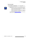
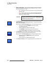
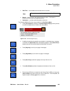
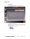
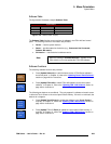
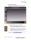
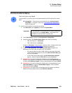
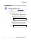
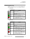
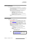
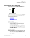
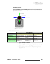
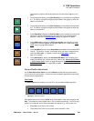
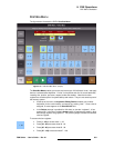
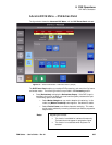
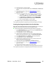
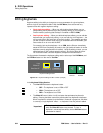
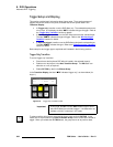
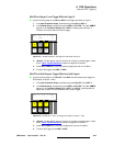
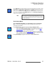
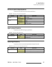
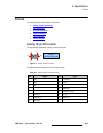
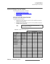
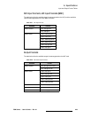
8. Press {Error Reporting} to turn error reporting on or off.
~ When on, if an input experiences an error, the connector turns red on the
rear I/O view, the input’s
Programmable Display turns red, and the
“
Error” button appears.
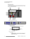
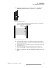
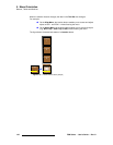
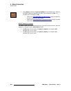
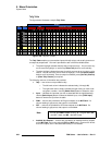
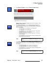
~ When off, the input’s Programmable Display remains green and the
red “
Error” button does not appear. The connector remains red.
10
Note
Remember that after a factory reset, UIC inputs are not
mapped to the panel, but default names are assigned.
Important
The system allows you to map an input to more than one
button. If an input is already mapped to a button and you
wish to map it to another location, use the
{Un-map} function
to remove the button from the unwanted location.
Note
The {Error Reporting} function works on a connector by
connector basis.