


30 FSN Series • User’s Guide • Rev 01
NK==fåíêçÇìÅíáçå
Connectivity Diagrams
`çååÉÅíáîáíó=aá~Öê~ãë
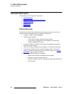
The following connectivity diagrams are provided in this section:
• System 1 — Basic
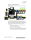
• System 2 — Multiple Destinations
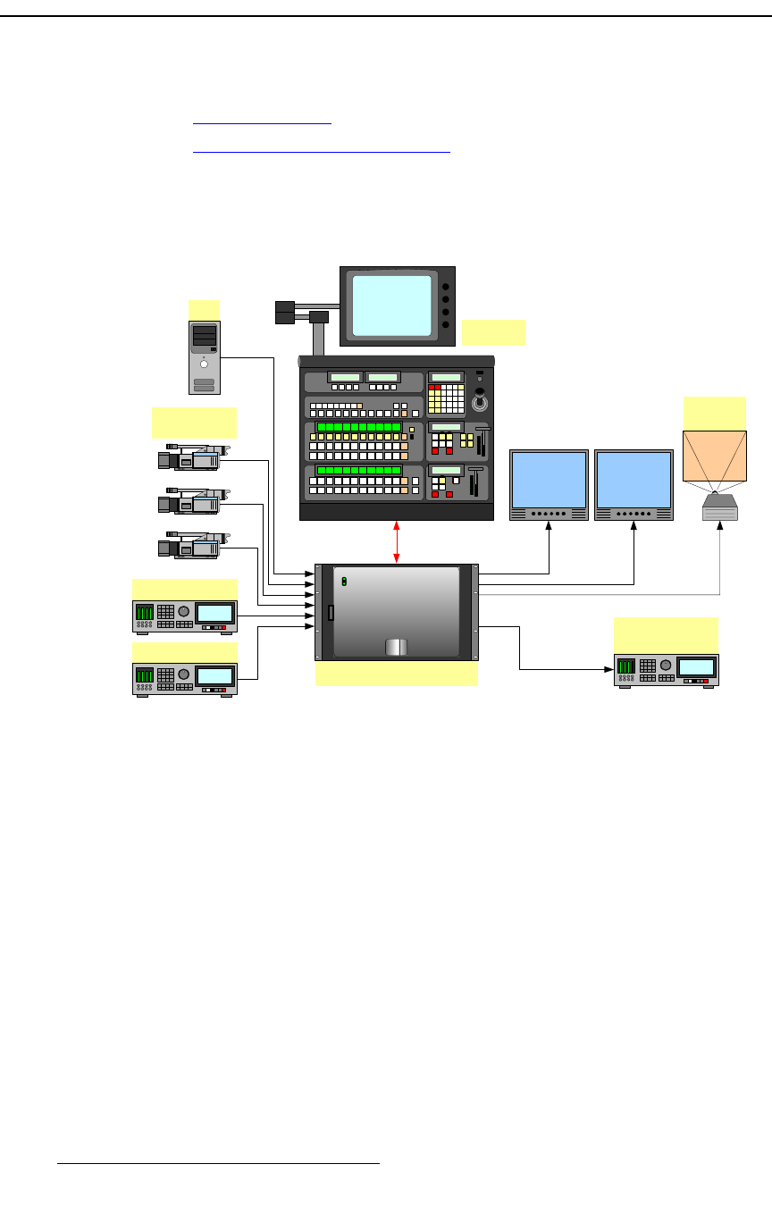
póëíÉã=N=Ô=_~ëáÅ
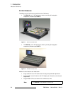
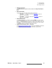
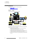
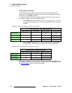
The figure below illustrates a basic FSN Series system:
Figure 1-3. Block diagram, basic FSN Series system (sample)
This configuration is an ideal basic setup consisting of multiple inputs, a single destination
output and a single Aux output. In the diagram:
• Multiple scaled and un-scaled sources connect to the FSN-1400, including
cameras, PCs, VTRs, DVRs and servers.
• The FSN-1400 and FSN-150 control panel connect via Ethernet.
• Program and Preview monitor outputs enable the TD to view the entire output of
the switcher, and preview the “look” that’s coming next on all outputs.
• The switcher’s SDI (SD-SDI or HD-SDI) Program output connects to the projector.
• One Aux output is connected to a VTR, providing the ability to record the output of
the event.
FSN-150
Program
Screen
PC
VTR / DVR
FSN-1400
Ethernet
Cameras
Analog / Digital
Server
Program Preview
Aux 1
Program Record