


100 FSN Series • User’s Guide • Rev 01
3. Control Panel Orientation
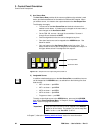
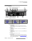
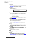
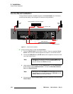
Control Panel Rear
6) DVI Connector
One DVI connector is provided to connect the control panel to the Touch Screen.
Use the supplied cable harness for interconnection. In Appendix A, refer to the
“DVI-I Connector” section on page 440 for pinout details.
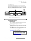
7) CPU Switch
The CPU Switch is located inside the small hole. This switch is designed for
qualified service personnel only.
8) Ethernet Port 1
One RJ-45 connector is provided for 10/100BaseT Ethernet communications.
Port 1 is connects to the FSN-1400, either directly or via an Ethernet Switch. By
default, the following conditions are set:
~ DHCP = OFF
~ Default IP address: 192.168.0.5
~ Default Netmask: 255.255.255.0
The user can use the default address, or set a different address. In Appendix A,
see the “Ethernet Connector” section on page 441 for pinouts.
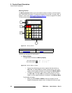
9) Ethernet Port 2
One RJ-45 connector is provided for 10/100BaseT Ethernet communications.
Port 2 can be connected to an outside network, or to your facility’s “house”
network. By default, the following conditions are set:
• DHCP = ON
An IP address can be obtained automatically from the outside network. In
Appendix A, see the “Ethernet Connector
” section on page 441 for pinouts.
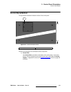
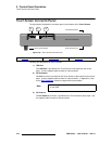
10) USB Ports
Four USB ports are provided. Use one of the four ports to connect data to the
Touch Screen, using the supplied cable harness for interconnection. The
remaining ports can be used for connecting customer-supplied USB drives, or if
required, to connect a mouse and keyboard.
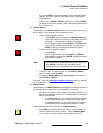
11) DC Power Out
One DC Power Out connector is provided for the Touch Screen power. Use the
supplied cable harness for interconnection.
12) Audio Connectors
The three audio connectors are not supported.
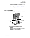
13) Fan
One Fan is provided for control panel cooling. To prevent overheating, do not
block the vent.
14) AC Power
One AC Connector is provided for connecting the control panel to AC. The
integral switch turns the panel on and off. In Appendix A, refer to the “Physical
and Electrical Specifications” section on page 435 for power details.
Important
Do not use this switch unless instructed to do so by Barco
Customer Service personnel.