FSN Series • User’s Guide • Rev 01 129
4. Installation
Signal Connections
jìäíáîáÉïÉê=`çååÉÅíáçåë
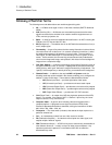
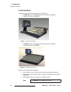
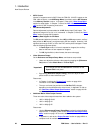
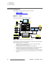
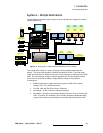
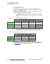
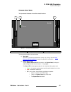
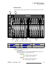
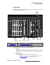
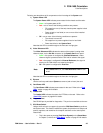
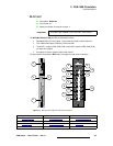
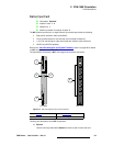
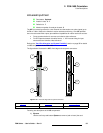
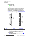
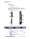
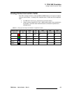
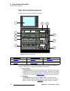
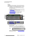
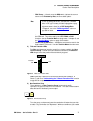
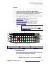
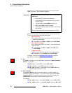
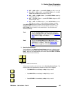
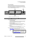
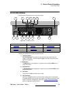
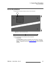
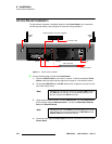
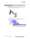
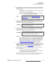
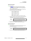
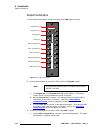
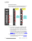
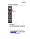
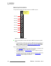
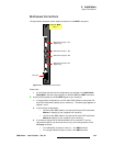
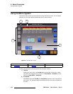
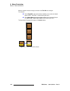
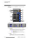
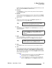
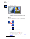
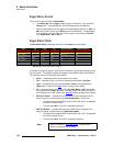
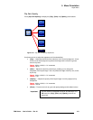
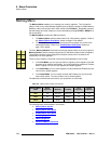
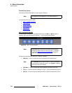
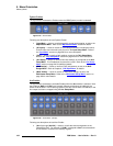
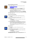
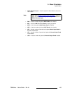
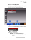
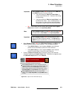
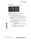
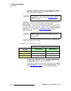
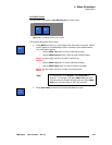
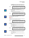
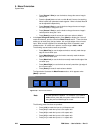
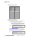
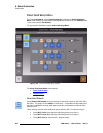
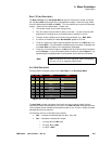
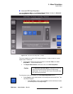
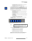
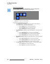
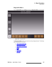
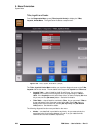
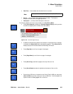
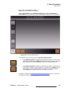
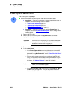
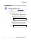
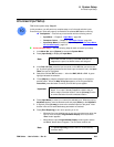
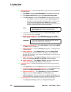
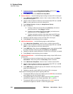
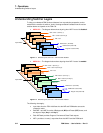
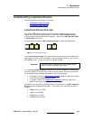
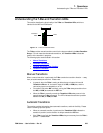
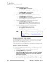
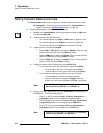
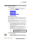
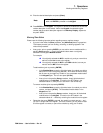
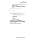
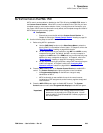
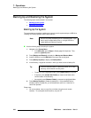
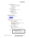
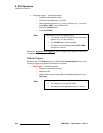
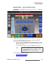
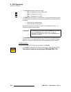
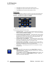
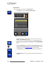
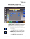
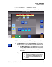
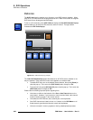
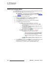
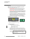
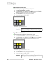
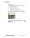
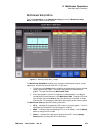
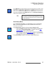
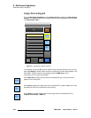
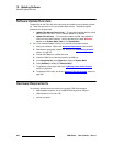
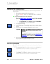
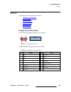
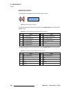
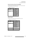
The figure below illustrates monitor output connections on the MVR’s rear panel:
Figure 4-20. Universal input connections
Please note:
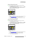
• In both single and dual monitor configurations (as selected on the Multiviewer
Setup Menu), the same signal appears on both the DVI-I and BNC connectors.
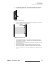
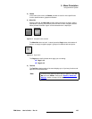
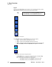
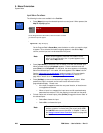
Use the following steps to connect MVR outputs to your monitor(s).
1. In single monitor configurations, use DVI and/or BNC cables to connect the DVI
and/or SDI multiviewer output(s) to your monitor(s). The same signal appears on
outputs 1 and 2.
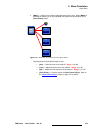
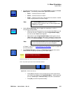
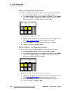
2. In dual monitor configurations:
~ Use DVI and/or BNC cables to connect the DVI and/or SDI multiviewer
Monitor 1 output(s) to your assigned “left” monitor(s).
~ Use DVI and/or BNC cables to connect the DVI and/or SDI multiviewer
Monitor 2 output(s) to your assigned “right” monitor(s).
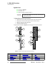
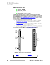
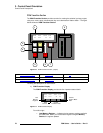
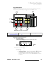
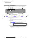
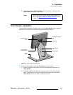
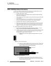
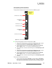
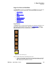
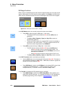
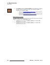
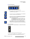
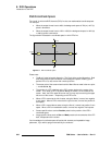
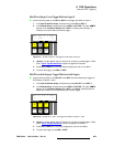
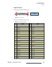
3. If you want to display time on the Multiviewer from an external LTC source,
connect the output of your time code source (e.g., time code generator) to the
LTC Input as follows:
~ For a differential connection, use the +, – and GND terminals.
~ For a single-ended connection, use the + and GND terminals.
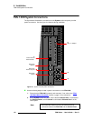
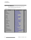
Multiviewer Output 1, DVI
Multiviewer Output 1, SDI
Multiviewer Output 2, SDI
Multiviewer Output 2, DVI
LTC Input
(Digital only)
(Digital only)
SDI
DVI Digital
DVI Digital
2
1
LTC Input
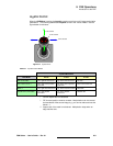
(Optional) MVR:
Slot 11