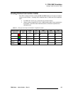
74 FSN Series • User’s Guide • Rev 01
3. Control Panel Orientation
Control Panel Descriptions
mdj=_~åâ
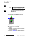
The PGM Bank is the switcher’s top video layer. The bank includes two physical buses
(PGM and PST), and one “phantom” KEY bus. Together, these buses are the switcher’s
primary location where you cut your program and transition to M/E setups. Please note:
• The PGM Bank has an associated PGM Transition Section to its right, where
effects and transitions (such as mixes, wipes and keys) are set up using the
sources selected in the buses.
• Using the Memory/Transition Section, you can store all or part of the PGM bank.
• The PGM Bank provides tally indications similar to the M/E. In Chapter 7, refer to
the “Understanding Tally” section on page 315 for details.
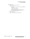
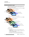
• The buses in the PGM Bank operate in “flip-flop” mode. In Chapter 7, refer to the
“Understanding Flip-flop Mode” section on page 314 for details.
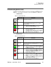
• Button color has important significance. In Chapter 7, refer to the
“Understanding Button Color” section on page 311 for details.
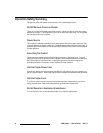
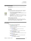
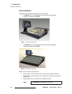
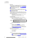
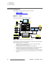
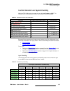
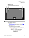
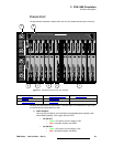
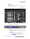
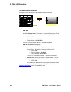
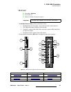
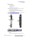
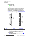
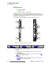
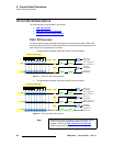
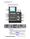
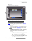
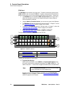
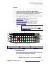
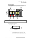
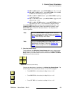
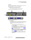
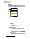
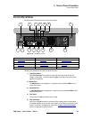
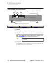
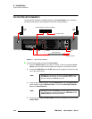
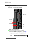
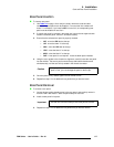
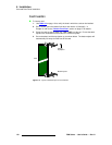
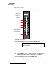
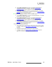
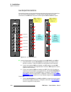
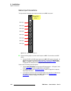
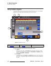
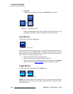
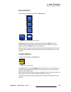
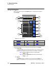
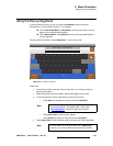
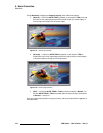
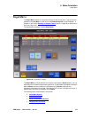
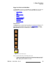
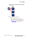
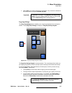
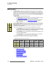
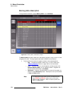
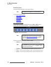
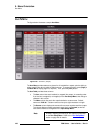
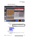
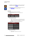
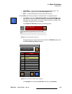
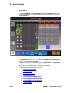
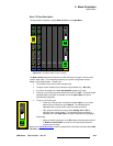
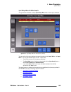
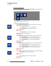
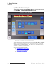
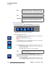
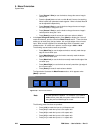
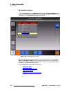
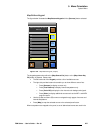
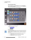
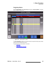
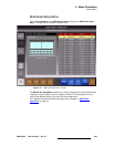
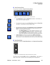
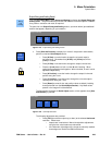
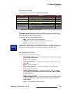
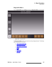
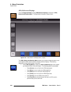
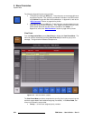
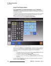
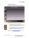
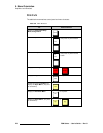
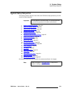
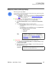
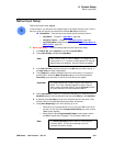
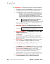
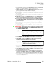
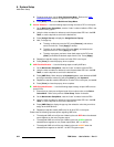
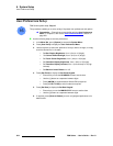
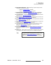
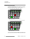
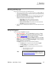
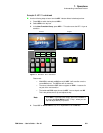
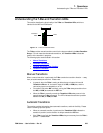
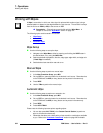
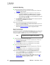
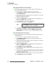
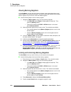
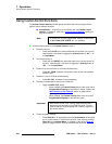
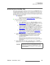
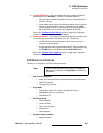
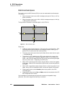
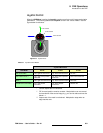
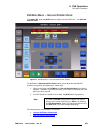
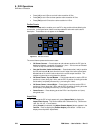
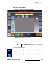
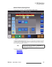
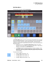
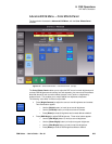
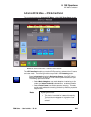
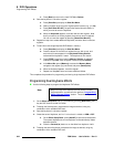
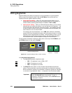
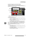
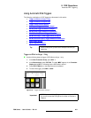
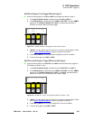
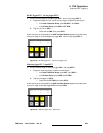
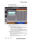
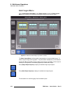
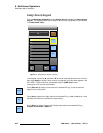
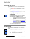
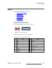
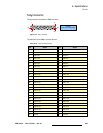
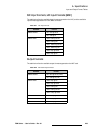
The figure below illustrates the PGM Bank on the FSN-150.
Figure 3-5. PGM Bank, FSN-150
Following are descriptions of each section:
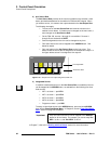
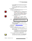
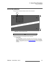
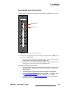
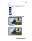
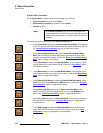
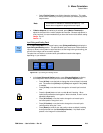
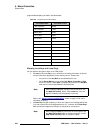
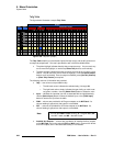
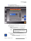
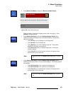
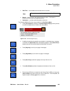
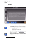
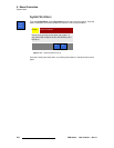
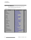
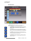
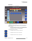
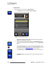
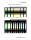
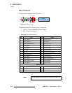
1) Programmable Displays
Above each source button on the PGM Bus, a Programmable Display shows
the source names that are assigned during setup (e.g., CAM1, VTR2, etc.). The
labels are dynamic — if the source is mapped to another button, the label follows.
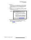
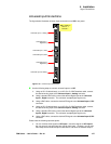
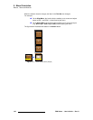
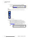
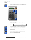
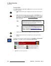
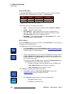
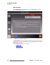
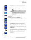
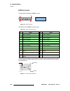
If an error occurs to either the shifted or unshifted input, the Programmable
Display turns red. In Chapter 7, refer to the “Understanding Error Messages
”
section on page 316 for full details.
P
G
M
P
S
T
DSK Assign
M/E
M/E
PGM
BLACK
SHIFT
BLACK
SHIFT
CAM1
GFX1
CAM2
GFX2
CAM3
VTR1
VTR3
VTR2
DVD1
DVD2
PC1
PC3
PC2
STL1
COL1
STL2
COL2
3
2
1
4
5
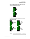
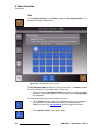
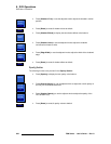
1) Programmable Displays 4) Re-entry Buttons
2) Program Bus 5) SHIFT Buttons
3) Preset and Phantom Key Bus
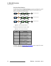
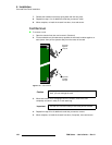
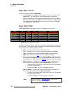
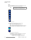
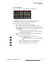
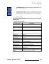
Note
In the Programmable Displays, the top row is the unshifted
source, the bottom row is the shifted source.