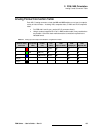
92 FSN Series • User’s Guide • Rev 01
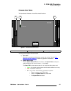
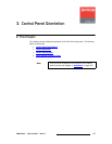
3. Control Panel Orientation
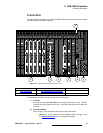
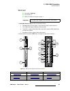
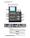
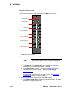
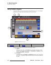
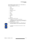
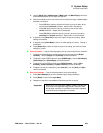
Control Panel Descriptions
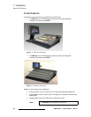
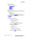
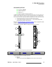
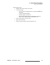
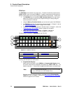
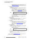
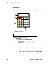
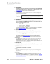
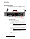
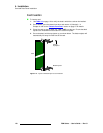
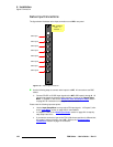
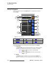
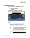
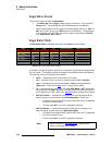
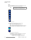
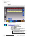
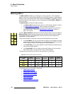
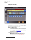
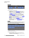
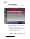
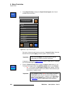
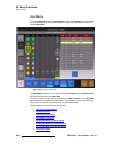
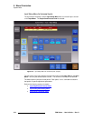
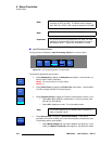
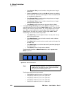
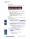
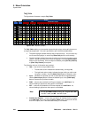
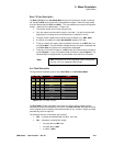
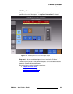
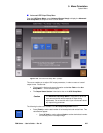
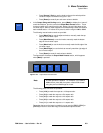
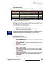
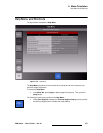
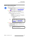
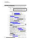
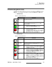
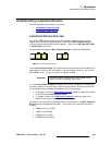
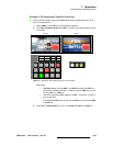
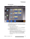
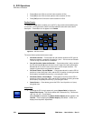
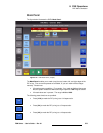
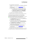
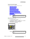
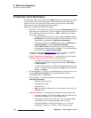
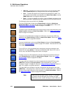
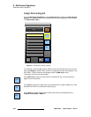
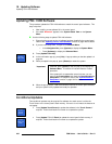
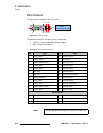
2) Aux Source Row
The Aux Source Row provides all the sources available on the switcher’s main
buses, plus dedicated buttons for the switcher’s PGM and M/E outputs. When
you select a source, it is routed to the output selected on the Aux Output Row.
The following rules apply:
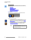
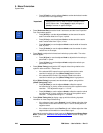
~ The sources on the Aux Source Row are identical to those on the
switcher’s main buses. If a button map is changed on the main rows, it
also changes on the Aux Source Row.
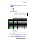
~ On the FSN-150, sources 1 through 10 are unshifted. Sources 11
through 20 are accessed via SHIFT.
~ Source assignments on the row can be changed at any time.
~ One clean feed source can be mapped to the ASSIGN button. See
below for details.
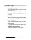
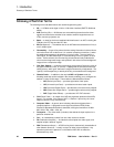
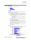
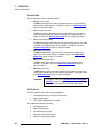
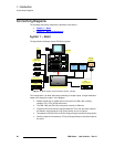
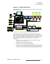
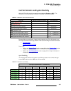
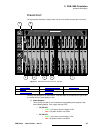
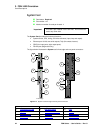
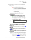
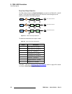
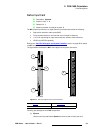
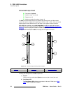
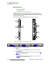
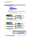
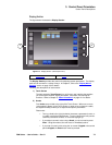
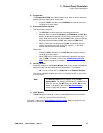
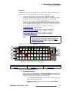
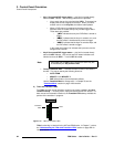
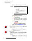
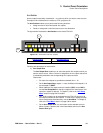
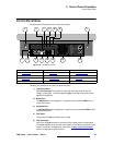
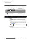
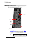
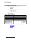
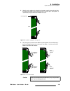
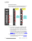
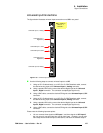
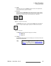
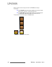
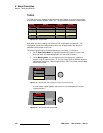
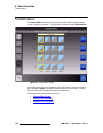
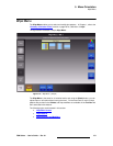
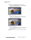
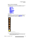
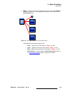
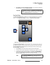
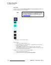
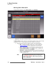
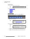
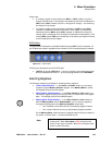
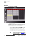
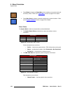
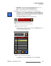
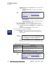
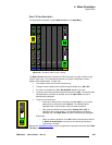
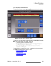
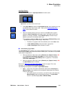
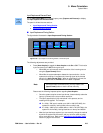
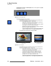
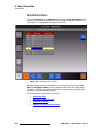
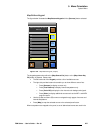
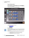
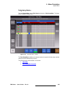
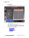
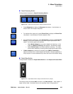
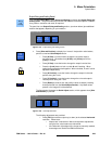
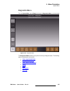
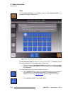
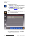
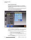
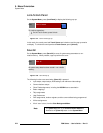
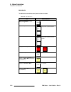
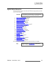
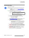
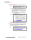
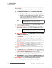
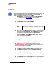
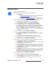
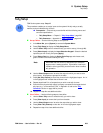
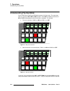
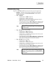
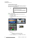
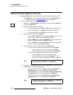
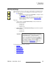
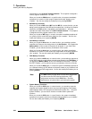
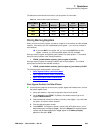
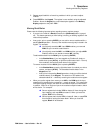
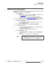
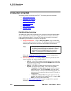
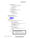
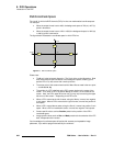
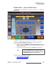
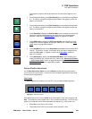
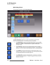
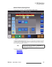
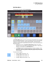
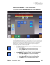
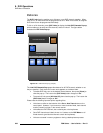
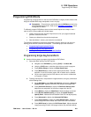
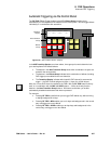
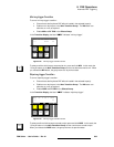
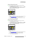
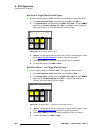
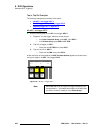
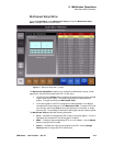
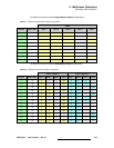
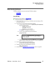
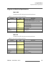
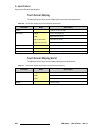
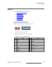
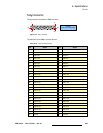
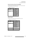
~ Only one button on the Aux Source Row can be lit at a time. This
button shows the source that is assigned to the selected Aux output. In
the figure below, source 2 is assigned to Aux output 2:
Figure 3-19. Sample source-to-output assignment, FSN-150
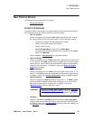
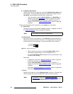
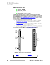
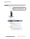
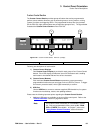
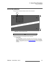
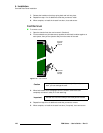
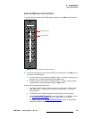
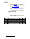
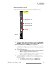
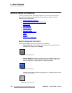
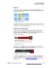
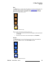
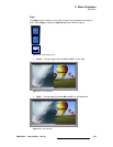
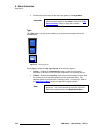
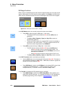
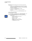
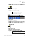
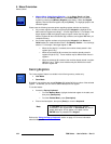
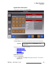
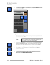
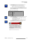
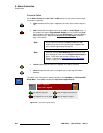
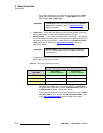
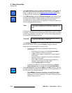
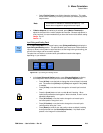
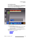
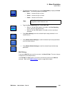
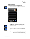
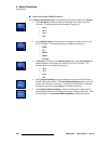
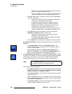
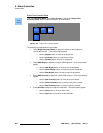
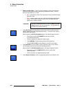
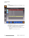
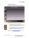
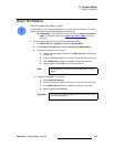
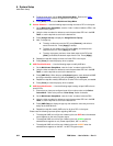
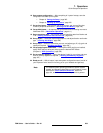
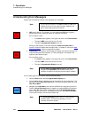
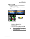
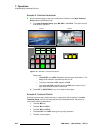
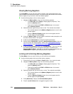
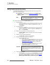
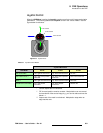
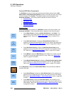
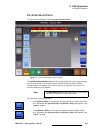
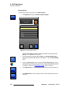
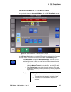
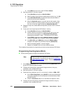
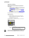
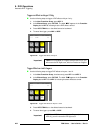
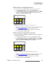
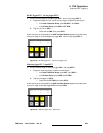
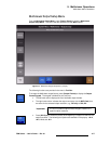
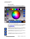
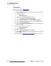
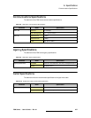
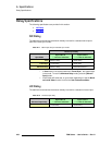
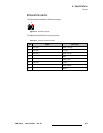
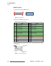
3) Assignable Source
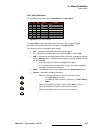
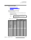
In addition to dedicated sources on the Aux Source Row, one additional source
can be mapped to the ASSIGN button, as selected from the following five clean
feed sources:
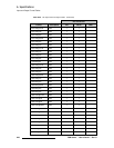
~ M/E 1 out clean — pre KEY 1
~ M/E 1 out clean — pre KEY 2
~ M/E 2 out clean — pre KEY 1
~ M/E 2 out clean — pre KEY 2
~ Program out clean — pre DSK
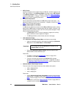
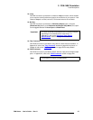
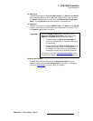
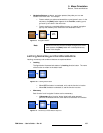
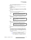
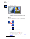
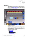
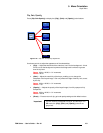
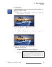
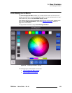
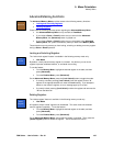
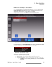
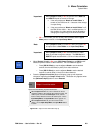
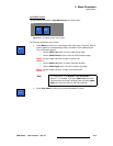
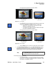
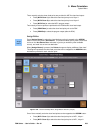
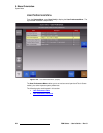
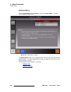
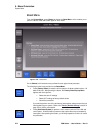
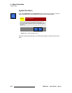
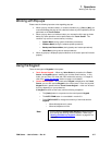
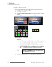
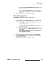
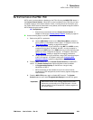
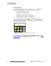
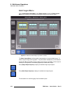
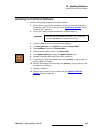
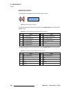
To assign a clean feed source to the ASSIGN button, press and hold ASSIGN,
then use the Clean Feed Setup Menu. In Chapter 5, see the “Clean Feed Setup
Menu” section on page 232 for details.
In Chapter 7, refer to the “Working with Aux Buses
” section for more information.
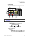
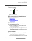
AUX
BLACK
1
9
2
10
3
11
4
12
5
13
6
14
7
15
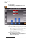
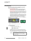
Aux Source Row
Aux Output Row
ASSIGN
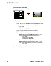
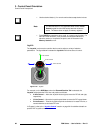
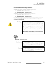
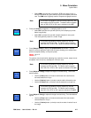
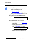
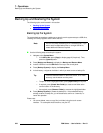
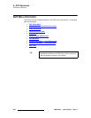
Important
Only one clean feed source can be mapped to the ASSIGN
button for all Aux buses. For example, you cannot map “Pre
KEY 1” to Aux 1, and “Pre KEY 2” to Aux 2.