


FSN Series • User’s Guide • Rev 01 31
NK==fåíêçÇìÅíáçå
Connectivity Diagrams
póëíÉã=O=Ô=jìäíáéäÉ=aÉëíáå~íáçåë
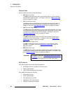
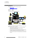
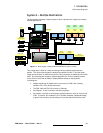
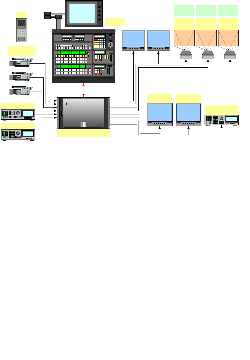
The figure below illustrates a sample system in which individual Aux outputs are routed to
different destinations.
Figure 1-4. Block diagram, multiple destination FSN Series system (sample)
This configuration is ideal for a setup consisting of three projected images behind a
podium. The left and right images are identical (as switched on M/E 1), and the center
image can be identical, or different from the two “wing” projectors (as switched on the PGM
bank). By connecting Aux outputs to different projectors, the TD has complete creative
control over the look, with the ability to display different setups on the projectors.
In the diagram:
• Multiple scaled and un-scaled sources connect to the FSN-1400, including
cameras, PCs, VTRs, DVRs and servers.
• The FSN-1400 and FSN-150 connect via Ethernet.
• Aux outputs 1, 2 and 3 connect to the three projectors.
• Aux outputs 4, 5 and 6 are connected to peripheral devices, such as monitors and
VTRs. In practice, this enables the TD to provide completely independent stage
or green room monitors, plus the ability to record the output of the entire event.
Aux 1
M/E 1
Aux 2
PGM
Aux 3
M/E 1
PC
Aux 4
Green Room
VTR / DVR
Ethernet
Cameras
Analog / Digital
Server
Program Preview
Aux 5
Production
Aux 6
ISO Camera Record
Center
Screen
Right
Screen
Left
Screen
FSN-150
FSN-1400