


FSN Series • User’s Guide • Rev 01 39
2. FSN-1400 Orientation
Hardware Description
`Ü~ëëáë=cêçåí
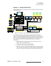
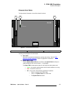
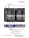
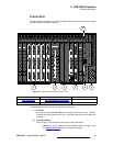
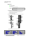
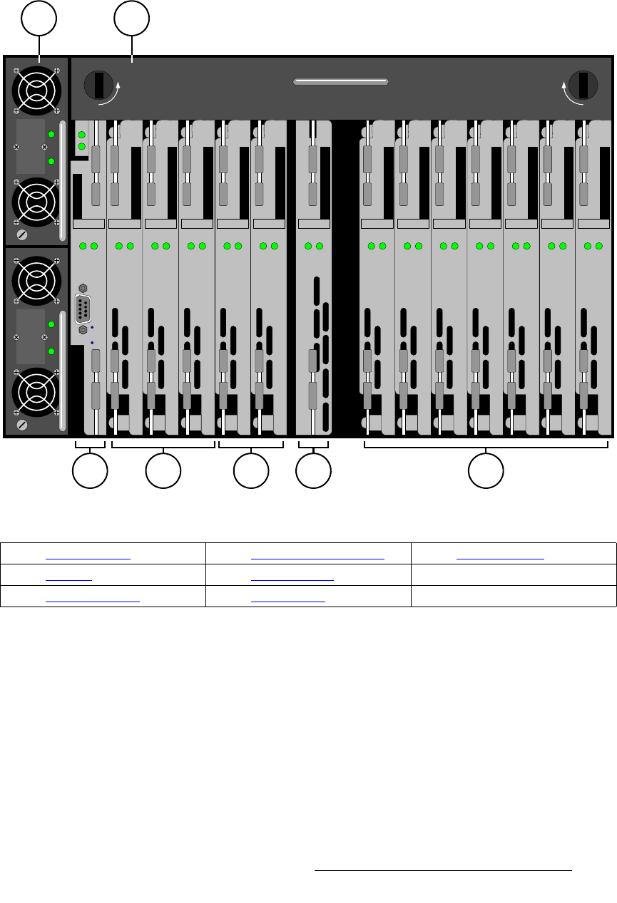
The figure below illustrates a sample front view of a fully-loaded chassis (door removed):
Figure 2-2. FSN Series chassis, front view (sample)
Following are descriptions of each section. Note that slots are numbered from right to left,
to correlate with the associated rear slots.
1) Power Supplies
Two slots are provided for dual redundant hot-swappable power supplies, each
with a 600W capability. Each supply has two LEDs:
~ DC OK LED:
• Green = DC power (from the supply) is OK.
• Red = DC power is bad or has failed.
~ AC OK LED:
• Green = AC power (into the supply) is OK.
• Red = AC power is bad or has failed.
12345678910111213Slot: 14
DC OK
AC OK
DC OK
AC OK
Power
Loaded
RS-232
CPU
IP
SYS
System Card
Power
Loaded
Native Aux Output Card
NAC
Power
Loaded
Native Input Card
NIC
Power
Loaded
Universal Input Card
UIC
Power
Loaded
Universal Output Card
UOC
Power
Loaded
DVE Card
DVE
Power
Loaded
Mix / Effects Card
M/E
Power
Loaded
DVE Card
DVE
Power
Loaded
Universal Input Card
UIC
Power
Loaded
Universal Input Card
UIC
Power
Loaded
Universal Input Card
UIC
Power
Loaded
Universal Input Card
UIC
Power
Loaded
Native Input Card
NIC
UNLOCK UNLOCK
WARNING: Operating the unit without the fan
tray will cause overheating and possible damage.
Power
Loaded
Multiviewer Card
MVR
1
6
2
3 74 5
1) Power Supplies 4) Aux and MVR Card Slots 7) Input Card Slots
2) Fan Tray 5) DVE Card Slots
3) System Card Slot 6) M/E Card Slot