124 FSN Series • User’s Guide • Rev 01
4. Installation
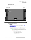
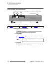
Signal Connections
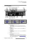
^ìñ=lìíéìí=`çååÉÅíáçåë
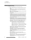
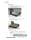
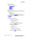
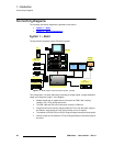
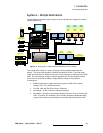
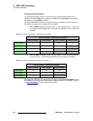
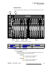
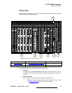
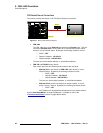
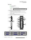
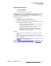
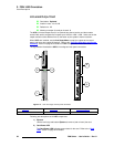
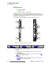
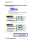
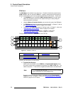
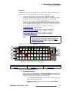
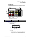
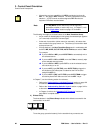
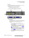
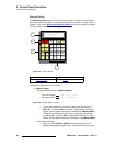
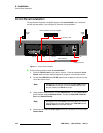
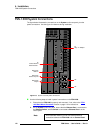
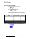
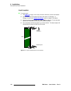
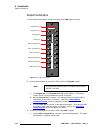
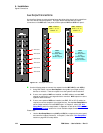
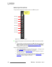
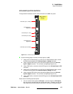
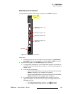
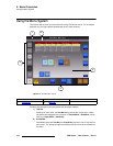
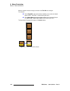
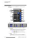
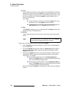
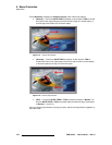
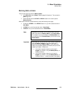
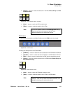
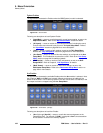
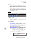
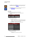
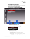
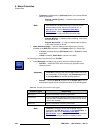
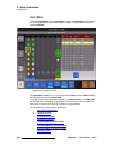
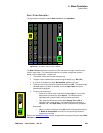
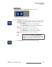
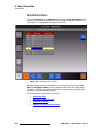
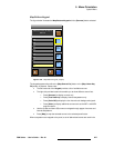
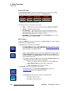
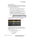
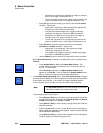
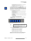
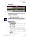
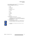
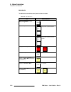
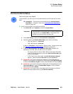
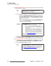
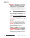
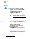
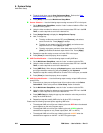
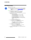
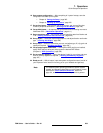
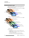
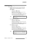
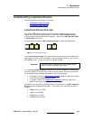
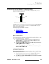
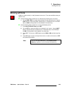
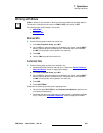
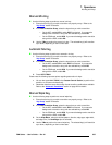
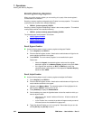
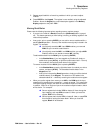
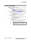
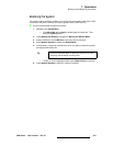
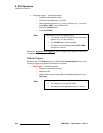
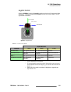
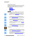
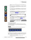
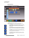
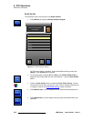
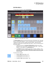
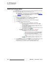
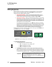
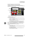
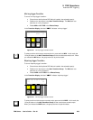
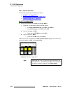
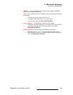
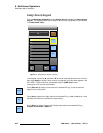
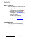
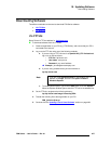
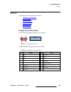
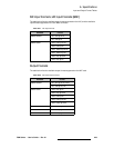
Aux (auxiliary) buses are extra switching buses that allow video signals to be routed from
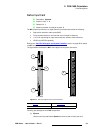
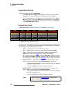
the FSN-1400 to external equipment. The figure below illustrates the Aux output
connections on the M/E card’s rear panel, and the optional NAC and UOC rear panel:
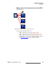
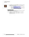
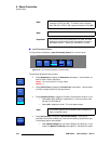
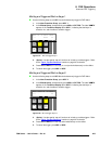
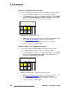
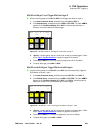
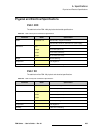
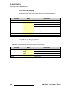
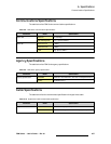
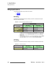
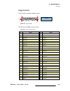
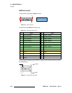
Figure 4-16. Aux output connections
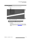
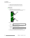
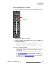
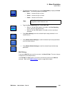
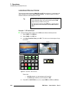
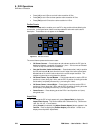
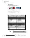
Use the following steps to connect Aux outputs from the M/E, NAC(s) and UOC(s).
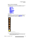
1. Using BNC cables, connect Aux Outputs 1 through 6 to your target auxiliary
devices or monitors. These six outputs run at the system’s native resolution.
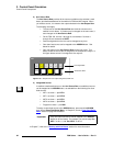
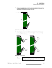
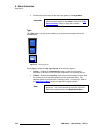
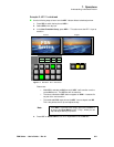
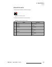
2. If one or more optional NACs are installed, use BNC cables to connect NAC
outputs (as required) to your target devices or monitors. NAC outputs run at the
system’s native resolution.
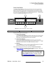
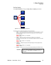
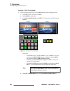
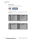
3. If one or more optional UOCs are installed, use BNC, DVI or HD-15 cables (as
required) to connect outputs to your target devices. Use the Aux Setup Menu to
set the output resolution for each UOC output. In Chapter 5, refer to the “Aux
Setup Menu” section for setup details. In Appendix A, refer to the “UIC Input and
UOC Output Formats” section for a list of available output formats.
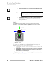
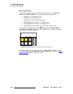
Please note:
• Use the Aux Setup Menu to map NAC and UOC Aux outputs to the control panel,
and name Aux outputs (if desired). In Chapter 5, refer to the “Aux Setup Menu”
section on page 240 for setup details.
Aux Out 1
Aux Out 2
Aux Out 3
Aux Out 4
Aux Out 5
Aux Out 6
2
CLN
Fill
PVW
PVW
PGM
CLN
1
PGM
CLN
3
4
5
6
M/E 2
CutPVW
M/E 1
AUX
DSK
PGM
1
2
3
4
5
6
7
8
SDI
SDI
AnalogDVI Digital
Analog DVI Digital
2
1
UOC - installs in
slots 11, 12, 13
NAC - installs in
slots 11, 12, 13
Note:
Use the
Aux Setup Menu
to map
all NAC outputs
Note:
Use the
Aux Setup Menu
to map
all UOC outputs
and set the
output resolution
Default: 13
Default: 12