


FSN Series • User’s Guide • Rev 01 127
4. Installation
Signal Connections
råáîÉêë~ä=fåéìí=`çååÉÅíáçåë
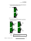
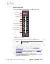
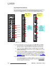
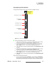
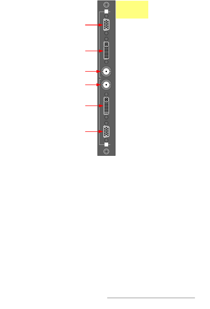
The figure below illustrates universal input connections on a UIC’s rear panel:
Figure 4-19. Universal input connections
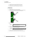
Use the following steps to connect universal inputs to a UIC.
1. Using an HD-15 cable directly, or an HD-15 to 5 x BNC breakout cable, connect
the desired analog input to the Universal Input 1, Analog connector.
2. Using a standard DVI cable, connect the desired digital input to the Universal
Input 1, Digital connector. The connector accepts digital signals only.
3. Using a BNC cable, connect the desired SDI signal to the Universal Input 1, SDI
connector.
4. Using an HD-15 cable directly, or an HD-15 to 5 x BNC breakout cable, connect
the desired analog input to the Universal Input 2, Analog connector.
5. Using a standard DVI cable, connect the desired digital input to the Universal
Input 2, Digital connector. The connector accepts digital signals only.
6. Using a BNC cable, connect the desired SDI signal to the Universal Input 2, SDI
connector.
Please note the following important points:
• You can connect three signals to UIC Input 1, and three signals to UIC Input 2,
but you can only use one signal at a time for each input. However, you can also
store setup files for different input combinations, and recall the desired setup to
Universal Input 1, Analog
Universal Input 1
Universal Input 1, SDI
SDI
AnalogDVI Digital
Analog DVI Digital
2
1
Universal Input 2, SDI
Universal Input 2
Universal Input 2, Analog
Digital only
Digital only
UIC - installs in
Slots 3 - 7
Default: 7