106 FSN Series • User’s Guide • Rev 01
4. Installation
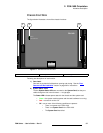
Control Panel Installation
`çåíêçä=m~åÉä=fåëí~ää~íáçå
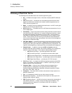
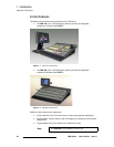
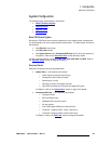
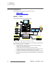
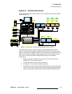
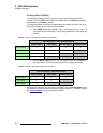
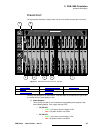
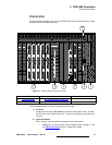
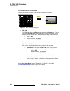
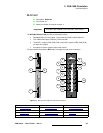
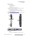
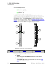
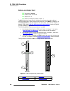
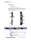
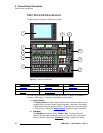
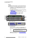
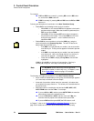
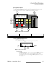
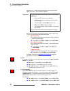
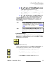
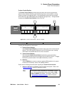
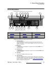
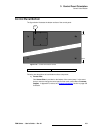
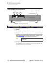
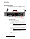
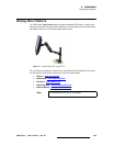
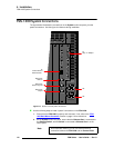
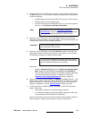
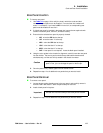
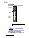
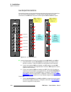
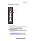
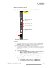
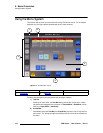
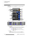
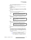
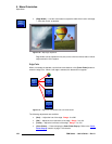
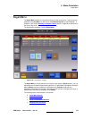
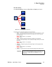
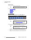
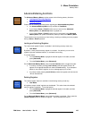
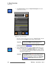
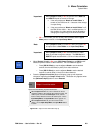
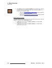
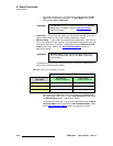
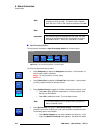
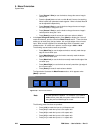
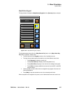
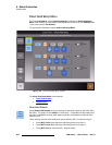
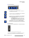
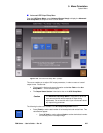
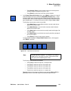
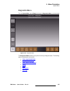
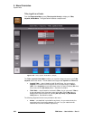
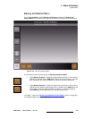
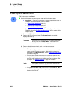
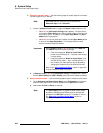
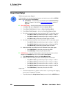
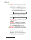
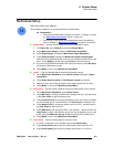
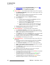
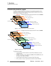
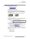
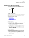
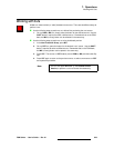
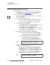
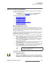
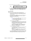
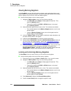
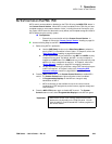
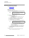
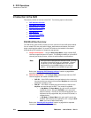
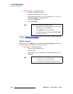
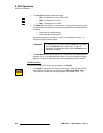
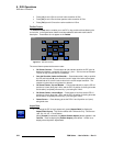
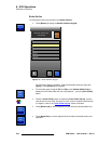
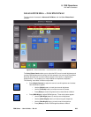
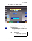
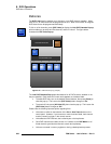
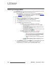
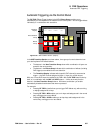
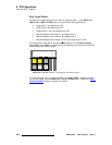
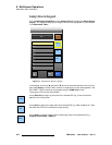
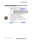
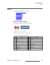
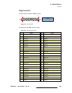
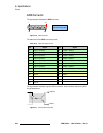
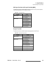
The figure below illustrates a simplified diagram of the Control Panel’s rear connectors,
and the required cabling. Use this figure for reference during installation.
Figure 4-1. Control Panel Installation
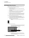
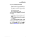
Use the following steps to install the Control Panel:
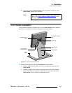
1. Place the Control Panel on your desk or console. Place the assembled Touch
Screen, stand and cable harness adjacent to the panel, in the desired location.
2. Connect the USB, DVI-D and 12V DC cables to their respective connectors on the
rear of the Control Panel.
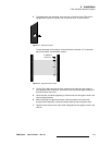
3. Using standard Ethernet cables, connect Ethernet Port 1 on the Control Panel
to the customer supplied Ethernet Switch. Connect the FSN-1400’s Ethernet
Port to the Ethernet Switch.
4. Connect the two supplied Script Lights to the XLR connectors on the rear of the
Control Panel.
100 - 240 VAC
50 - 60 Hz
2.3A
12V DC OUT 1.5A
CPU
Ethernet
Port 1
Ethernet
Port 2
Light Light
Cable Harness
To Touch Screen
AC
DVI-D
USB
12V DC
Script
Light
Script
Light
To FSN-1400
Ethernet Switch (customer supplied)
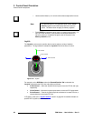
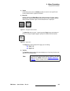
Note
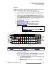
Although you can use any of the four available USB ports for
the USB cable connection, it is recommended that you use
the port closest to the DVI-D connector.
Note
Although the use of the Switch is recommended, you can use
a direct Ethernet connection between the FSN-1400 and the
Control Panel as an alternate method.