FSN Series • User’s Guide • Rev 01 91
3. Control Panel Orientation
Control Panel Descriptions
^ìñ=pÉÅíáçå
An Aux output is essentially a destination — a location to which you want to route a source.
Examples of Aux destinations are monitors, VTRs, projectors, etc.
The Aux Section enables you to perform the following functions:
• Assign sources to native and scaled Aux outputs.
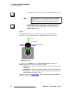
• Route an “assignable” clean feed source to an Aux destination.
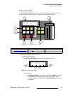
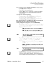
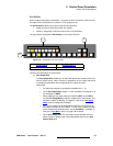
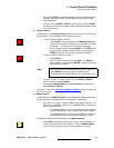
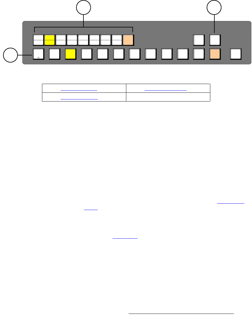
The figure below illustrates the Aux Section on the model FSN-150:
Figure 3-18. Aux Section, FSN-150 (sample)
Following are descriptions of each section:
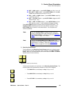
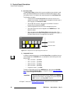
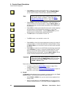
1) Aux Output Row
The Aux Output Row enables you to select the specific Aux output to which you
want to route a source. When a source is assigned to an Aux output, that source
is immediately switched to the corresponding Aux output connector.
Please note:
~ Six native Aux outputs are provided as standard (Aux 1 - 6).
~ On the Aux Output Row, outputs 1 - 8 are unshifted, while outputs 9 - 16
are accessed via SHIFT.
~ When additional Aux output cards are installed (UOCs and/or NACs),
use the Aux Setup Menu to map Aux outputs to the control panel, and
name Aux outputs (if desired). In Chapter 5, refer to the “Aux Setup
Menu” section on page 240 for details.
~ Only 16 Aux outputs can be switched from the FSN-150, but up to 30
Aux output channels can be installed. To view all Aux outputs and their
source assignments simultaneously, use the Aux Menu. In Chapter 5,
refer to the “Aux Menu
” section on page 186 for details.
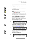
~ On the Aux Output Row, only one button can be selected at a time.
When a button is pressed, the current associated source on the Aux
Source Row lights.
AUX
ASSIGN
PGM
BLACK SHIFT M/E
1
9
2
10
3
11
4
12
5
13
6
14
7
15
8
16
SHIFT
2
3
1
1) Aux Output Row 3) Assignable Source
2) Aux Source Row


