FSN Series • User’s Guide • Rev 01 125
4. Installation
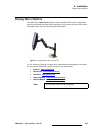
Signal Connections
bñíÉêå~ä=aph=fåéìí=`çååÉÅíáçåë
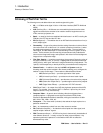
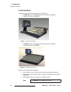
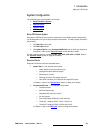
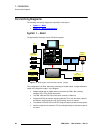
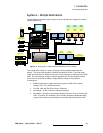
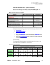
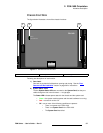
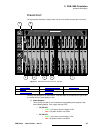
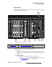
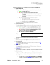
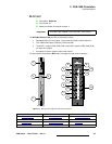
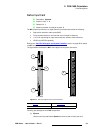
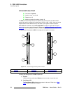
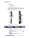
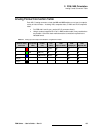
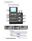
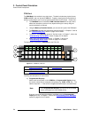
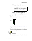
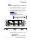
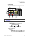
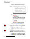
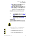
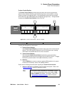
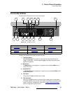
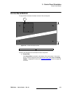
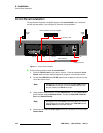
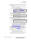
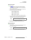
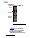
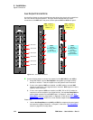
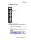
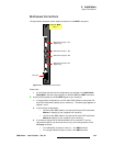
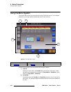
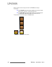
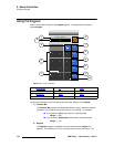
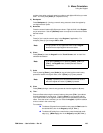
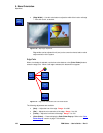
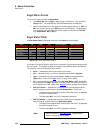
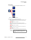
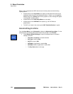
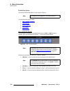
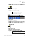
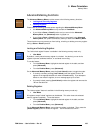
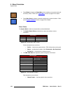
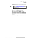
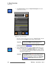
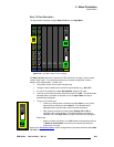
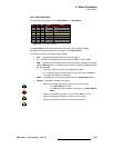
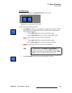
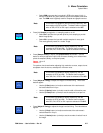
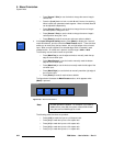
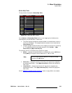
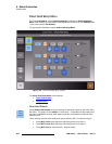
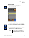
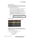
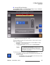
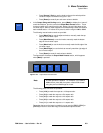
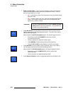
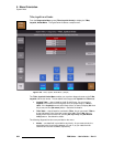
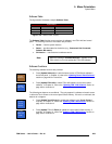
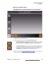
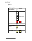
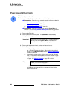
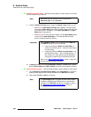
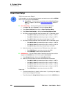
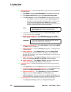
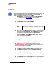
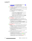
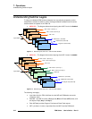
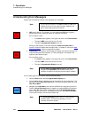
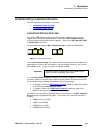
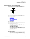
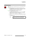
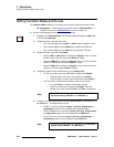
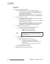
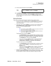
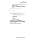
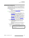
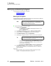
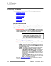
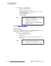
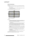
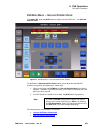
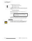
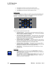
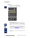
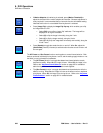
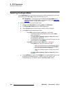
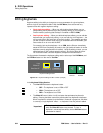
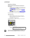
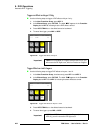
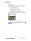
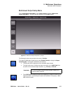
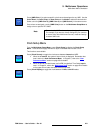
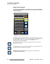
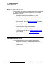
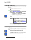
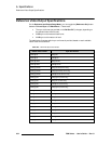
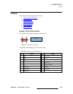
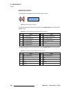
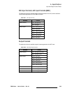
The figure below illustrates external DSK input connections on the M/E card’s rear panel:
Figure 4-17. External DSK cut and fill connections
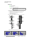
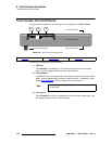
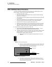
Use the following steps to connect external DSK cut and fill signals to the M/E card. All
connections use BNC cables.
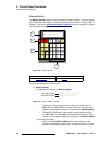
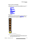
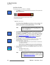
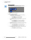
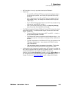
1. Connect an external cut signal to the Cut connector. This type of signal typically
originates from a character generator’s Cut or Key output.
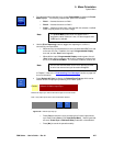
2. Connect an external fill signal to the Fill connector. This type of signal typically
originates from a character generator’s Fill or Video output.
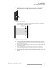
Please note the following important points:
• The DSK Cut and Fill inputs must be locked to the same video reference as the
FSN-1400 chassis. SAV (start of active video) must be within +/- 0.5 lines of
frame reference.
• The DSK Cut and Fill signals must be set to the system’s native resolution.
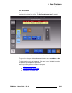
• Use the External DSK Setup Menu to set up the signals. In Chapter 5, refer to
the “External DSK Setup Menu” section on page 229 for menu details.
• In Chapter 6, refer to the “External DSK Input Setup” section on page 296 for
step-by-step setup instructions.
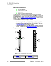
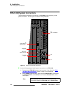
External Cut In
External Fill In
2
CLN
Fill
PVW
PVW
PGM
CLN
1
PGM
CLN
3
4
5
6
M/E 2
CutPVW
M/E 1
AUX
DSK
PGM