FSN Series • User’s Guide • Rev 01 203
5. Menu Orientation
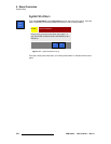
System Menu
oÉ~ê=fLl=sáÉï=aÉëÅêáéíáçå
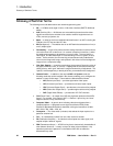
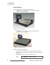
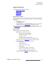
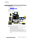
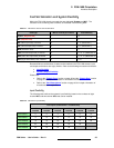
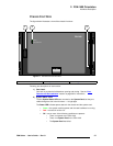
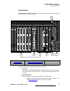
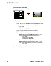
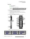
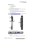
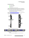
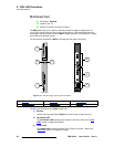
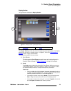
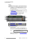
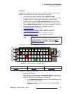
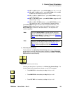
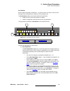
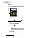
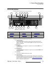
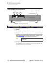
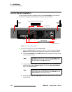
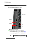
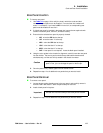
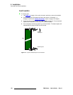
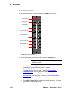
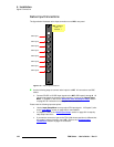
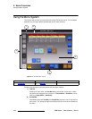
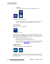
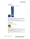
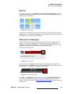
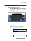
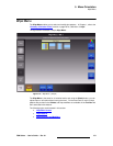
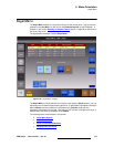
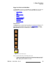
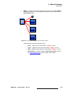
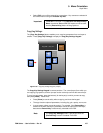
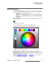
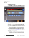
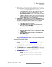
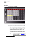
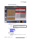
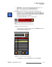
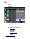
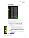
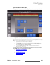
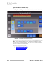
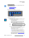
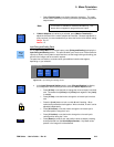
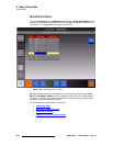
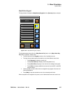
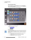
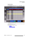
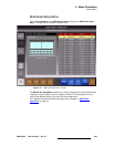
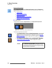
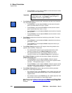
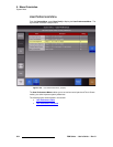
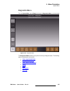
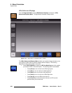
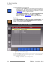
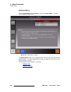
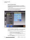
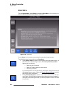
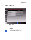
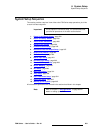
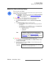
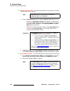
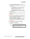
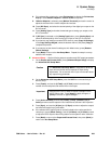
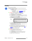
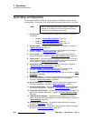
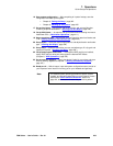
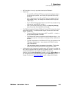
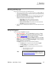
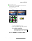
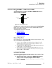
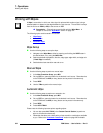
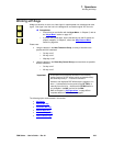
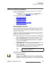
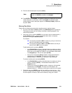
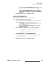
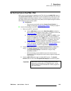
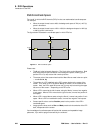
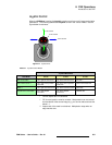
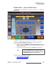
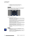
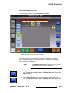
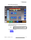
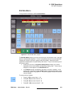
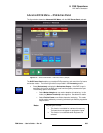
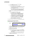
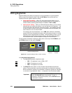
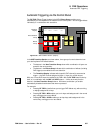
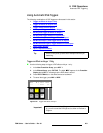
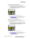
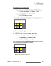
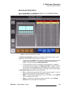
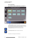
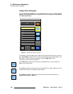
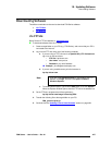
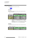
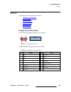
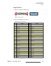
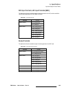
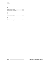
The figure below illustrates a sample Rear I/O View on the Input Menu:
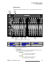
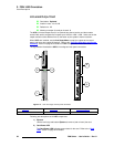
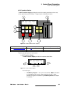
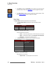
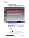
Figure 5-82. Input Menu, Rear I/O View (sample)
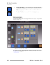
The Rear I/O View shows the I/O panels for FSN-1400 slots 1 through 7, which can be
used for input cards. This view always matches your system configuration exactly —
based on the installed cards. Please note:
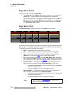
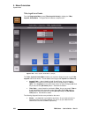
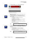
• The number of each slot is shown along the top.
• The type of each installed card is shown along the bottom (e.g., NIC, UIC).
• If a card is not installed, the label “Not Installed” appears in the slot.
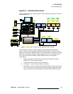
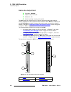
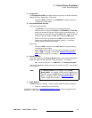
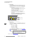
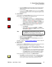
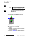
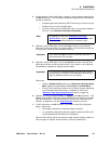
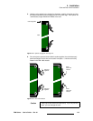
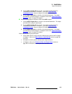
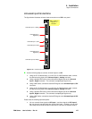
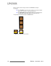
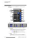
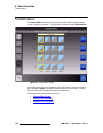
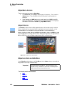
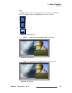
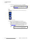
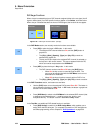
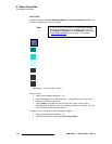
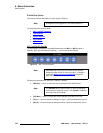
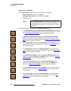
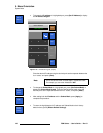
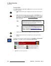
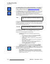
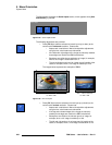
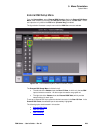
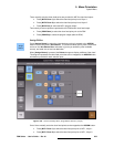
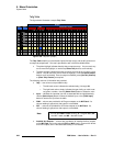
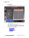
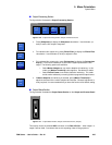
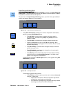
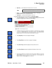
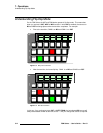
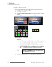
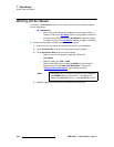
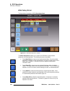
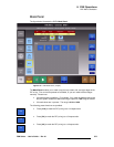
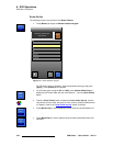
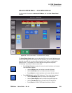
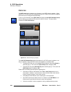
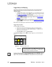
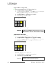
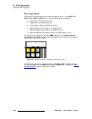
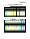
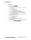
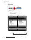
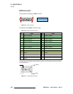
• To set up a native input, press the desired connector on a NIC. The yellow border
indicates that the connector is selected, and in the
Input Table, the input is
automatically highlighted.
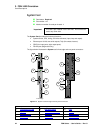
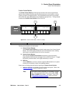
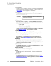
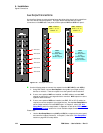
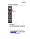
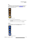
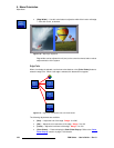
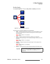
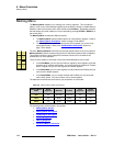
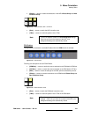
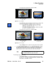
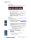
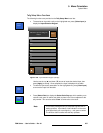
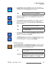
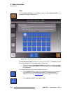
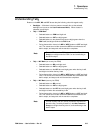
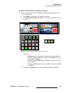
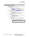
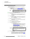
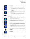
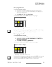
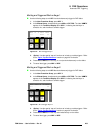
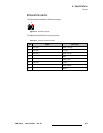
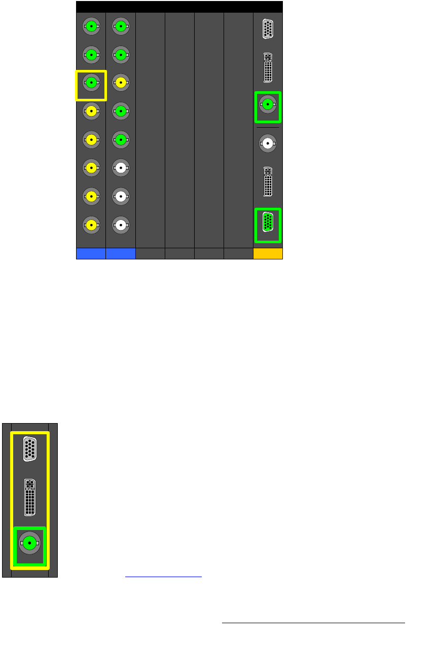
• To set up a universal input:
~ Press any of the top three connectors to select Input 1, or any of the
bottom three connectors to select
Input 2. The selected input is
highlighted with a yellow border around all three connectors.
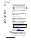
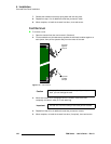
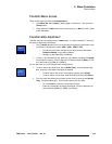
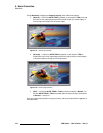
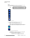
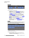
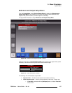
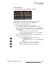
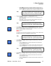
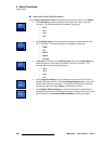
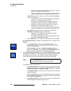
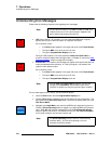
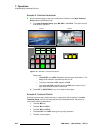
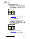
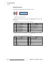
~ Next, press the desired connector (either Analog, DVI or SDI) to
highlight it with a green border. This indicates that the connector is
selected, and in the
Input Table, the input is automatically highlighted.
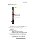
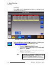
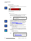
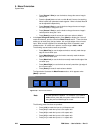
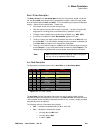
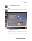
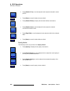
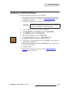
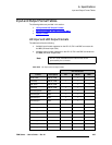
Please note:
~ When you switch connectors on the UIC, freeze will always be turned off.
If “
Black on Invalid Video” is turned on, the input will go black as it
acquires the new input.
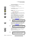
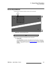
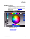
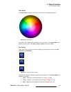
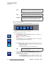
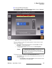
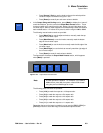
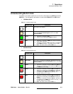
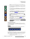
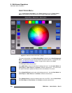
Refer to the “
Connector Colors” section on page 204 for important information about Rear
I/O View
connectors.
Slot 1
NIC
Slot 2
NIC
Slot 3
UIC
Slot 6
Slot 7
Not
Installed
Not
Installed
Not
Installed
Not
Installed
1
2
8
7
6
4
5
3
1
2
8
7
6
4
5
3
Slot 4 Slot 5
Analog 1
DVI 1
SDI 1
SDI 2
DVI 2
Analog 2
Analog 1
DVI 1
SDI 1