


102 FSN Series • User’s Guide • Rev 01
3. Control Panel Orientation
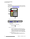
Touch Screen Connector Panel
qçìÅÜ=pÅêÉÉå=`çååÉÅíçê=m~åÉä
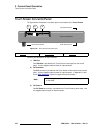
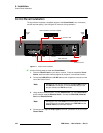
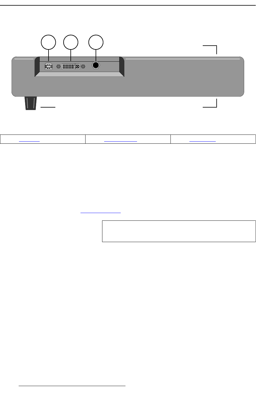
The figure below illustrates the connector panel on the bottom of the Touch Screen:
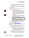
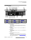
Figure 3-26. Touch Screen Connector Panel
Following are descriptions of each connector:
1) USB Port
One USB Port is provided for the Touch Screen’s data input from the control
panel. Use the supplied cable harness for interconnection.
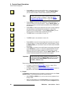
2) DVI Connector
One DVI connector is provided for the Touch Screen’s video input from the control
panel. Use the supplied cable harness for interconnection. In Appendix A, refer
to the “DVI-I Connector” section on page 440 for pinout details.
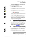
3) DC Power In
One DC Power In connector is provided for the Touch Screen’s power input. Use
the supplied cable harness for interconnection.
1 2 3
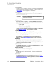
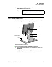
Touch Screen Rear
Touch Screen Bottom
Touch Screen FrontTouch Screen Knobs
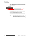
1) USB Port 2) DVI Connector 3) CPU Switch
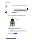
Note
This is a digital only input. There are no analog components
on the cable.