


FSN Series • User’s Guide • Rev 01 205
5. Menu Orientation
System Menu
fåéìí=q~ÄäÉ=aÉëÅêáéíáçå
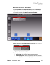
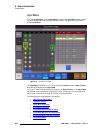
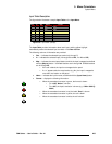
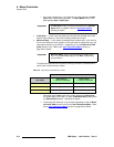
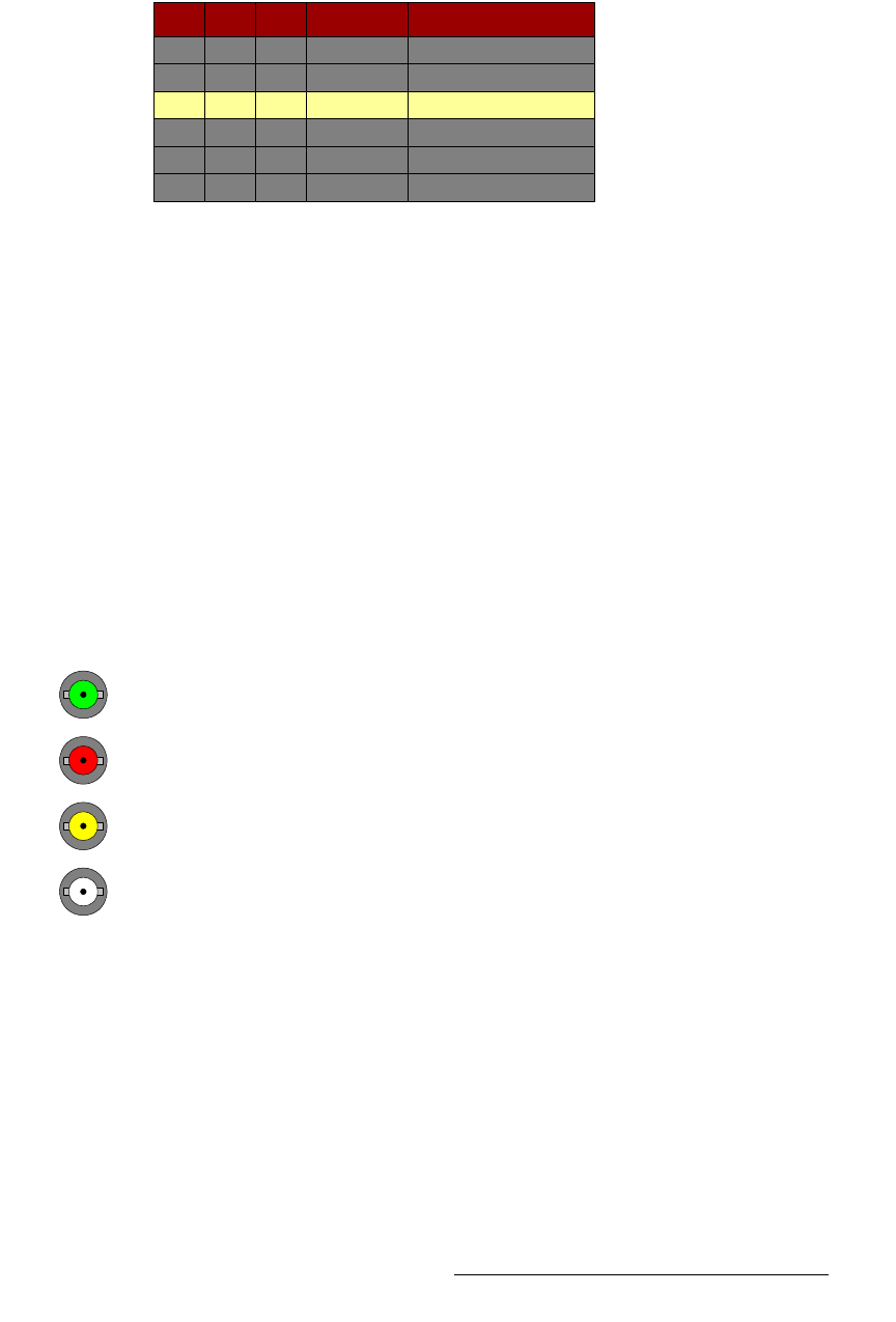
The figure below illustrates a sample Input Table on the Input Menu:
Figure 5-84. Input Table (sample)
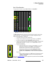
The Input Table provides information about each input, and the yellow highlight
automatically tracks the selected input connector in the
Rear I/O View.
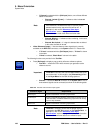
The following columns of information are provided:
• Slot — indicates the selected input card slot (1 through 7).
• In — indicates the selected input (1 through 8 for a NIC, 1 or 2 for a UIC).
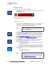
• Map — indicates the control panel button to which the input is mapped, as defined
with the
{Map to} button. Unshifted locations are 1 through 10. Shifted locations
are
11 through 20.
~ If the cell is blank, the input is not mapped to the panel.
~ If a “+” appears after the map location (e.g, 2+), the input is mapped to
more than one location on the panel.
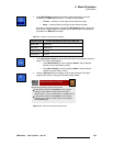
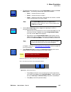
• Name — indicates the input’s name, as defined with the {Input Name} button.
• Format — displays the following information:
~ When the associated connector is green, the format is shown:
• For a
NIC, “Native” is shown.
•For a
UIC, the input’s resolution is shown (e.g., 1920 x 1080i @
59.94).
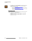
~ When the associated connector is red, the label “Error” is shown.
~ When the associated connector is yellow, the cell is blank.
~ When the associated connector is white, the cell is blank.
Slot
1
1
1
1
1
1
Map Name
CAM1
CAM2
CAM3
1
2
3
Format
Native
Native
Native
In
1
2
3
4
5
6