


FSN Series • User’s Guide • Rev 01 63
2. FSN-1400 Orientation
Card Descriptions
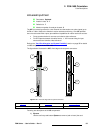
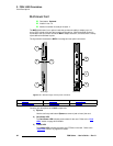
4) MVR Output 1
In order to provide multiviewer connections to both SDI and DVI compatible
monitors, two connectors are provided for MVR Output 1:
~ 1 x DVI-I
~ 1 x BNC
The same output signal appears on both the DVI-I and BNC connectors. MVR
Output 1 can be used in both single and dual multiviewer monitor configurations,
as selected on the Multiviewer Setup Menu:
~ In a single monitor layouts, the selected layout appears identically on
MVR Output 1 and MVR Output 2.
~ In a dual monitor layouts, one half of the selected layout appears on
MVR Output 1, and the other half appears on MVR Output 2.
Please note:
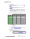
~ The output resolution for both MVR outputs is set on the Multiviewer
Output Setup Menu, using the Output Format Keypad.
~ Both the BNC and DVI-I connectors can be active at the same time,
provided that the selected format is compatible. The valid combinations
are fully listed in the Output Format Keypad.
~ Refer to Chapter 9, “Multiviewer Operations” on page 411 for full
multiviewer setup details.
5) MVR Output 2
Output connections for MVR Output 2 are identical to MVR Output 1. See above
for details.
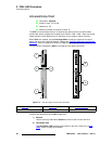
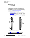
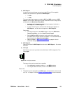
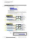
6) LTC Input
One Phoenix connector is provided for the Multiviewer’s LTC (Longitudinal Time
Code) Input.
Figure 2-14. LTC Input connector
Two types of time code connections are possible:
~ For a differential connection, use the +, – and GND terminals.
~ For a single-ended connection, use the + and GND terminals.
Please note:
• Test patterns can be assigned to any MVR output, and a raster box can be turned
on or off. In Chapter 5, see the “Output Test Patterns Menu” section for details.